Canem's Grid Solar Install

Well it’s got a ways to go before it’s done, but there’s actually enough work done on my home solar array to start documenting the progress. It’s the same design as Syonyk with some minor hardware upgrades and tweaks for my ground: 2x ~7kw 20-panel systems, Sunny Boy 6.0 Inverters, all mounted on 1 long a-frame.

Drone shot of the space before anything got started, red marks the space the panels will go. That concrete pad is an old tower base from when this end of the valley used to all be commercial orchard. It’s easy enough to tie into, and just about the best spot to clear the trees and shop building to the west as best as possible.

But first, an un-necessary story from September 2022 that offers some excuse for why this took so long to get started.

1 Like

Roughly, yes, but one of the two “second generation” designs - the first has been in service up the hill from me for a while, and is a fairly massive 21kW system I really should go do a writeup on at some point.

The second gen designs are more aggressively cost optimized. My original design is based around strings of 12x 60 cell panels - the revised design is based around 10x 72 cell panels. Electrically identical, but the 72 cell panels are somewhat cheaper, and the 10x vs 12x count means the strings are physically shorter, for less mounting hardware.

They’re also based around metal frames and XR1000 rails, vs my wood and XR100 rails - longer spans between supports for less overall material.

In other words, closer to $1/W than my ~$1.50/W - mostly depending on wiring cost, which relates to “distance from interconnect.”

10 months…

It was ten months since I started looking for a rather critical component to get started on this solar install- a main-breaker/meter-base combo panel with suitable 225amp rated buss bar for back feeding.

It’s a breaker panel, should be easy to source right? Well what quaint pre-2020 thinking. There’s about a half-dozen models of panel/meter that would work on this house, and none of them could be found. According to 2 suppliers kind enough to call around for me, all suitable options were unavailable on this entire continent. So that kind of damped the progress there for a while. I made it a frequent habit of browsing electrical supply house websites, and calling around, and emailing, several times a month. Props to the places that actually answered my inquiries instead of the ones that just ignored me from message #1.

Anyway, ten months had gone by and now it was September, 2022. Did the usual habit and on the Home Depot site I saw something on the page of the Square D 816d200c [you bet I have all those model numbers memorized]: ‘limited stock available in Meridian’.

Well it was 5pm on a Wednesday… should I call and see if it’s true? Nah, it’s Home Despot, they’ll just tell me whatever the computer says. But like… what if? What if they really had one?

So I hopped in the car and began MY EPIC QUEST to find a breaker panel. It was almost an hour drive there, but I wasn’t going to let that stop me. Result? They didn’t have it… Computer says they have one in stock but ya know… rounding errors I guess?

But they tell me the Eagle store has ‘limited stock available’. So I drive up there aaaaand… they didn’t have it either :smiling_face_with_tear:, but they tell me one of the Boise stores has one, ‘probably’. So this time instead of driving another hour away from home I actually called the store. They didn’t pick up. So I called the pro desk, which rang and rang, and redirected to the main phone, which also didn’t pick up. I sent some messages to a friend to complain and nearly resigned myself to a failed quest before deciding to call one… more… time…

and they picked up! and told me the electrical guy was busy at the moment but if I’d give them the model # he’d call me back in 10-15 minutes. So I did that and continued sitting in a Home Depot parking lot waiting for a call from another Home Depot. 15 minutes later I get a call, “Hi uh, yeah I’m still up in a forklift basket, but can you tell me that model # you were looking for again and I’ll look for it and get back to you in a few minutes?” “[sighhh… certainly, I’m looking for a Square D 816d200c 200-amp outdoor breaker/meter base combo panel.”

5 minutes later and this adventure is feeling more like a hostage negotiation than a simple stock check. 6 minutes later I get a call: “Yeah I got one right here for you”, “…I don’t believe you. I mean… really?”

I will neither confirm nor deny setting a new landspeed record in a Honda Civic, but I did make it to the Boise HD store, and found waiting for me in a cart in the electrical isle, this glorious bit of hardware:

breakerpanel

Was that story helpful for those building their own grid-tie solar? Not a chance! But I had to wait 10 months for that moment so yall’s can just deal :stuck_out_tongue:

A-frame design

Instead of wood my a-frames are all steel. 1.5" galvanized sched 40 pipe, 9 of them, with spacing optimized for span and cantilever requirements for the Iron Ridge XR1000 rails that the panels will attach to.

So here’s half an a-frame, working out the geometry in CAD. That upper most set of parallel green lines are the dimensions for the REC solar panels, and the little rectangles underneath are the dimensions of the cross section for the XR1000 rails. I wanted the pipes in the ground a minimum of 24" deep and on the lowest end of the solar array I wanted 14" of clearance between the bottom of the panel and the ground. The hill I live on is a north-facing slope, and I’m building this array to be level, so that will increase towards the north.

The CAD work here helped me work out the minimum needed pipe while still having clearance between the panels at the peak of the A-frame and make sure the XR1000 could be mounted the proper distance from the edges of the solar-panels per the REC panel’s specs.

Site layout

Scraped some dirt and weeds, and started laying out stuff with stringlines and marking paint. I started on the north end, marked a line where the panels would be (which overhangs about 2.5’ from the end A-frame).

Then the stringlines go it at the width where each hole for the post holes will be drilled.

So the first post hole gets marked, and on one side it’s just a matter of marking down one side where the posts will go. The next trick is to get the post holes on the other side to be properly square with the first side.

Find a friend and some reel-tapes. We pulled them out and put the ends on each post hole to the left and right of the one being marked, and just move them until they intersect each other at the same dimension and the stringline on the far side.

Quickest way I could find to layout a square line at distance anyway. Clear as mud? Cool, moving on.

So that’s 16 holes marked for 9 A-frames. The missing 2 are planted right over that concrete pad, so I’ll just be welding some baseplates onto that A-frame and wedge-bolting it to the pad instead of, ya know, trying to auger an 8" hole in a concrete block.

Those HDs probably did have one somewhere, but it were lost in the store. We found an entire pallet of Black Friday discount Milwaukee somethings one spring because the guy who I showed the app saying that they had 50 in stock would not take no for an answer.

He rounded up like four other workers and they spent 30 minutes looking at pallets and pulling them down until they found it wedged behind some other pallet, 40 feet up.

So there are a lot of things that it would be good to have adjustable in installing these a-frames, so that everything ends up aligned and straight and coplaner and all that good stuff. There is a fair range of adjustment built into the hardware from Iron Ridge, but I’d sooner have things aligned properly to begin with.

So the idea is this: set stringlines level with where the top of the vertical posts should be, and instead of trying to get them plumb, and the right width apart, and set the perfect distance above grade, eliminate one of those variables by setting everything 2"+ above the stringline. Later I’ll come back and cut them all flush with the string.

So then came time for concrete:

Did I mention I’m building this array with solar power too? Power for the field work is being done on the little solar trailer you can see in the background.

1 Like

When my house was getting a new panel (1950’s 90A!), I tried convincing the electrician to put in a 300 or 400A panel, but with 200A breakers for the grid connection because of the 120% rule. Sadly I failed, which is going to make my future upgrade plans more complicated.

The 2011 NEC 705.12(D)(2) 120% rule restricts a panel from receiving no more than 120% of its max rating. For example, if a panel with 200A bus bars has 200A breakers coming from the pole, the NEC will only allow me to hook up 40A (9.6kW) of PV to it.

(Why is 10kW too small? A 10 kW array can generate 26 kwh/day in winter (57 kwh/day in summer) where today we’re using -20 kwh/day. If we electrify one of our two cars (21k mi/yr @ 0.5 kwh/mi), that’s -28 kwh/day. If we electrify the furnace (1 therm/day @ 50% eff in a 1950’s furnace), that’s -19 kwh/day. So that’s ~66 kwh/day in winter. The CA tariffs keep changing such that aiming for net-zero-kwh annually may no longer be the optimal sizing method; less kwh/day from the grid with battery shifting may be better.)

The complication comes when I move past one generator to more than one (i.e. V2G), but in a off-grid/islanding scenario (V2H), I really need a subpanel so I can control what is (not) getting power during an outage. The SPAN panel by http://span.io/ comes to mind, but I worry whether they’ll still be around 20 years from now.

It’s worse. That “40A” backfeed is a non-continuous rating, so really, you can only have 32A of inverter.

Are you looking at roof mount or ground mount? A single Sunny Boy 7.7 is a 32A continuous output, so hanging like… 12-14kW of A-frame panel on it might be the cheapest option, if you can do ground mount.

It seems like there are some options without swapping your main panel;

  • AC coupled, but over-panel ~10 kW of inverters such that you will still produce enough in the winter. (I think this is what @Syonyk is alluding to - though it might take more than 14kW of panels depending on latitude and other factors.)
  • DC coupled (presumably with some battery capacity) with some of your loads on non-grid-tied inverters (and independent panel(s)/circuits), then only install grid-tied inverters up to at 10 kW limit.

(Correction: In Dec 2022, Jan, Feb 2023 I used 59, 71, 69 therms/mo to heat the house, dry clothes, heat domestic hot water, and cook. Summer drops to ~14 therms/mo so napkin math says that heating adds ~46 therms/mo or 1.5 therms/day)

Today, I average 20 kWh/day, but within the next 5 years I am adding:

  • +29 kWh/day peak electric use to heat the house (done)
  • +28 kWh/day electric car (one or two? not sure.)
  • +6 kWh/day domestic water heat pump (HPWH)
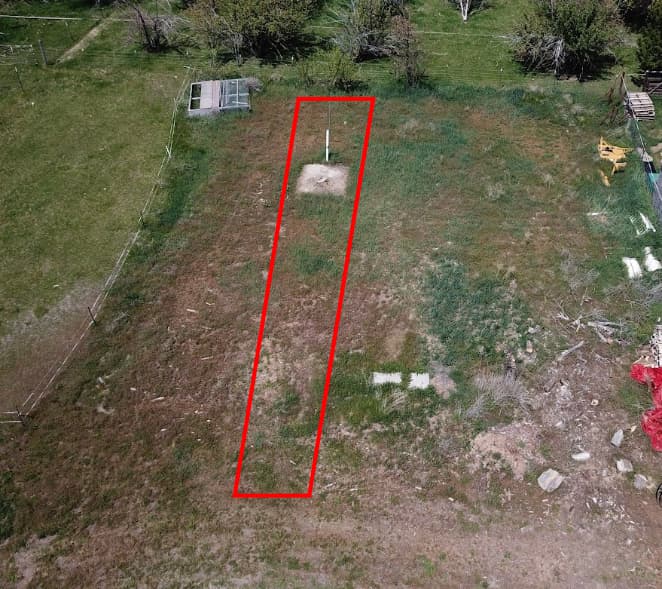
    With 2 cars, that totals 111 kWh/day! To aim for even 100 kWh/day in winter is a ~39 kW PV system. I doubt I could fit that on my 5,500 sq ft lot.

There’s several unknowns here.

Unrealistic: Sizing for peak usage is unrealistic, even if I were off grid. I’m in the middle of the Silicon Valley, so I can 99.9% rely on the grid (outages measured in single-digit hours) and plumbed natural gas; it merely costs money to buy energy. Or I need controls to remotely load shed without walking outside to flip breakers.

Unknown: The above are merely estimates. I haven’t started EV shopping, and I need to wait a year to find out how much our heat pump uses in summer and winter.

Unknown: When V2G and/or V2H become generally available?

Unknown: What will utility tariffs look like in 1-3 years? Using the grid as a battery based on the annual net generation can’t keep going.

Unknown: Does it make sense to convert to an electric clothes dryer? This is the least of these concerns. If the dryer currently uses 16k BTU/hr, that’s 6.25 hours of run per therm representing ~8 loads/week. We’re surely using less for two adults, but worst case, 1 therm/week = 4 kwh/day. I’d vaguely guess we’re in the 2.5-3 kwh/day representing 4-5 loads/week.

So my apologies; I’m not looking for a solution quite yet, I’m just thinking aloud.

The trick is having sufficient integration that can balance multiple energy sources (stationary battery, EV batteries, PV, grid, plus wind and/or backup generator for you off-grid folks) and has decent controls to control what mode you’re in (e.g. duck curve load shifting, don’t discharge car beyond x%, charge house battery from car battery with approval). Some demonstrators have been built, but in practice this isn’t available today.

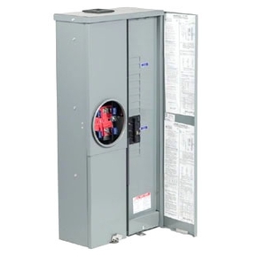
Lastly, someone recently pointed at an product that lets you remove the meter, and connect directly, thus bypassing the breaker panel bus bars. This lets you get around that 120% NEC rule. In theory, you could backfeed up to the main breakers’ rating.

How many miles a day do you drive? Do the EV math based on that, not based on [handwave] based on battery capacity. Figure 3mi/kWh and you’re close.

And, yes, “line side taps” go between the meter and the meter base. Just, not all utilities will let you use them. Mine won’t, for instance.

I was using 400 mi/week or 20.8k mi/year, but that doesn’t look right. I used to drive 20 mi/day for work 4 days a week plus 75 mi/day 2 days a week (work+trainer), but that’s only 230 mi/week = 12k/yr.

So ignoring trips, a “typical” week is less than half of what I was calculating. For abnormal long trips, we can supplement with charging stations, so it’s really only the daily drive that should be factored in.

230 mi/week / 0.346 kWh/mi, that’s 76.6 kWh/week or 11 kwh/day, down from 28 per car.

Better yet, I’m in the bay area. I should just get an ebike!

Aside from commuting to work and exercise, I bill about 300 mi/year for consulting. There’s a 500 mi round trip we make at least twice a year, errands once or twice a week (probably <20 mi/week or 1,040 mi/year) so I’m scratching my head why I thought I drove 20k mi/year.

So that revises peak winter use of 111 kWh/day down to 77 kWh/day or a 30kW PV array which is still ridiculously oversized.

I mean, you know my array size. I can generate 2 kWh/day on a bad winter inversion off the whole thing. Sizing for winter demands seems a bit odd to me for a grid tie system.

Personally? I’d just stuff 32A in with a pretty high DC:AC ratio, and accept that you’ll still have some power bill. Do the work yourself at $1.50/W or less and it stops mattering nearly so much.

Next was to stick a bunch of pipes in concrete. Square, plumb, and set 2" above the stringlines.

Did I mention I’m doing all the field-work for this project running off a solar-trailer? Building solar with more solar. The one exception was when I had to weld a few 1/4" baseplates and the welder needed 240v for that. Every things else has been done off that trailer- welding, sawing, grinding and drilling.

The design idea here is to have as much adjustability as possible at each stage of construction to compensate for how hard it can be to get things all lined up and set perfectly in concrete, especially on a hill like this. So to get everything vertically set perfectly, they’ll get cut down to level after being set intentionally too high.

While those are setting up, time to involve some 3D printed jig design!

So I made this little thing to help me cut the saddles on top of the posts. The stem sticking out the side is to fit a piece of 3/4 EMT conduit. I was going to use it as a cross-beam between two of them to keep things level between each 2 posts , but then I convinced myself I got everything lined up level and perfect with the stringlines so I didn’t use it.

But it works like this:

Line up the top with the stringline, and now I can mark out a guideline to cut the 30deg angles. Follow that up with way too much time hefting a large angle grinder and it looks like this:

Level, and easy to set the A-frames on top of. Making the A’s separate from the posts means I can set the first and last frames, run stringlines between those, then set the other a-frames up and just slide them left and right until they line up properly with the end frames.

Finally, some welding

Yeah doing this with gas and solid-wire MIG was a little silly but I’m out of Flux core…

A 7x16’ wood decked flatbed trailer can make an excellent fixturing table. I marked up and cut out the first 3 parts for an A-frame, laid those out, then cut up a 2x4 and screwed those blocks to the deck. Makes it very fast and accurate to make a bunch of the same part.

Then start cutting up 10 24’ sticks of pipe

2"x3/16"x24’ pipe starts to feel a little bit heavy about half way through that process.

Tacked together on the trailer and welded out on sawhorses.

And do all that 9 times.

Well it’s sure starting to look like… something.

So then I stood the end frames up, ran some stringlines and started to line up all the ones in between one by one.

That worked very, very well. The worst misalignment on 2 A’s was a little under 1.5", but most were well under 1". That’s plenty accurate, the hardware for attaching the Iron Ridge rails to these frames should be able to easily compensate for that.

And now it definitely looks like something!


The next day I came out and wirebrushed all the welds, and applied some cold-galvanized compound to them all. Basically just a zinc-rich spray paint.

1 Like

just a note on something i discovered while researching a ground mount system. they make a thing called ground screws which , for my area, needed to be 7’ long due to frost heave, and can be put in with a bobcat attachment. from what i saw, you can have them in very quickly.

Depends on your area, for sure.

Out here, they’ll get a foot down, and bind on some large rock that’s not moving.

Next bit of hardware acquired and installed. The Iron Ridge XR1000 rails.

Wasn’t going to pay the prices they wanted for their tube-mount bracket however. I already have some surplus 2"x2"x1/2" aluminum angle, so I started by drilling those for U-bolts and the Iron Ridge hardware.

Simple parts. Cut and drill, 36 times.

Then haul all the gear outside and start running stringlines again. Some slight tweaking was required to get the rails mostly ‘eyeball straight’, but overall the stringlines made it a quick job.

It was a warm day getting started on these already when the bee keeper’s truck pulled in to tend the hives that stay here in the late summer. I thought about calling it quits for the day as the bees can get rather cranky when having their hives heavily disturbed. Guess they were far enough away that they left me alone while the truck came and went.

These new model of BOSS [BOnded Structural Splice] doesn’t require screws. Instead it has this stainless spring-steel tab with some serrations in it that cut into the rails. No hardware required to secure them together, and it provides the grounding connection.

Starting to look like some fancy trusswork now.

All my A-frames turned out really well aligned except for one. That put more of a wave than I was comfortable with into the rails on one side, so I pulled those brackets and slotted out where the 7/16" hole was to provide extra adjustment.

Much better. The whole line looks pretty straight now.


So that’s all the rails installed. Next up will be figuring out a method of mounting the inverters to this south-most A-frame. That will probably require welding some DIN rails for mounting points, so I’ll do that so I don’t end up welding next to a bunch of installed solar panels. Might haul an inverter out this afternoon and at least get a plan going for how that will be assembled.

1 Like