Cool music reactive LED controller, F/OSS software, yay!

So I recently found WLED, a great F/OSS project for ESP controllers to control addressable LED strips/matrixes. Really cool features. And then I found Sound Reactive WLED fork, which makes it even cooler! Get ambient audio and have the FFT/etc already built into the code, with some preset color/animation choices which means I don’t have to try and be creative about that, which is not my strong suit. The SR WLED is for ESP32 only, but those are still generally relatively cheap and plentiful, and you can find various boards pre-flashed with WLED, including some with onboard mics. Nice!

Links to LedBox V2, which can be bought from tindie. Good hardware, good documentation, everything open source including design files. Basically everything you’d want from a hobbyist who saw a niche and felt like helping out folks and maybe even making a few $. Nice! Even has a resettable fuse for when powering LEDs through the device, and a proper buck-boost so you can power the board and LEDs up to 17v max. Needs LED voltage, so 5v/12v will be the most common.

Then while on Tindie I found this slightly cheaper version, that actually is thinner, although a bit longer, but will work better for 1 of my use-cases. Just thin enough, yay!

So I’ve got both, do some very basic tests with ambient music and an LED strip connected to each. Yup, works! The WLED Sync code (over WiFi UDP) also works, super sweet. So I can have one be the “primary” in AP mode on startup, and I power the other one up after and set it to the AP from the primary, and then they’ll sync animations and such, but when far enough away that the AP disconnects, it’ll fall back to it’s own thing.

However it was very obviously Chinesium, and it does have some issues. Takes forever to boot up. I’ve been trying to get serial commands working with the SR WLED 0.13.1 pre-release, and for some reason it just isn’t working (we actually think we’ve found the issue in the SR code, will test it out later tonight), so I ended up hooking up the Chinesium one to serial. Power it up, and I’m getting Brownout looping reset. Great. Talking with the seller, at least they’re fairly responsive which is nice, get down to the crux of the real issue.

Apparently the thing was originally designed to be 12-24v system, but some tests some time ago indicated it could run 5v just fine. ESP32 runs at 3.3v, so they have a LDO conversion to 3.3v, but of course that means it needs enough voltage above that to run properly without the voltage dipping too low. Well, apparently there is a diode on the board which is dropping it an additional 0.6V (along with other components) before it hits the voltage conversion sub-board. So when it starts up, the WiFi immediately starts up, and it sags the voltage to 3.11v and the thing browns out. So the sellers solution is to jump (short) the one diode which should let the voltage be back up high enough to run properly.

This way to use diode was adopted a long time ago for all our boards to reduce voltage input on LTO and then power dissipation in LTO that may burn when we need up to LTO limit (about 1 amp.) , in this case, you don’t really need that, remove or shunt it with confidence.

So yeah. Chinesium can be great, but then you run into trouble like this that just wastes your time.

So I’ll update here when I have some visible working hardware so ya’ll can see, but thought I’d share the tale of woes as well as cool F/OSS stuff for those that like pretty lights. There’s also a WLED Home-Assistant integration for those that run HA for smart home stuffs.
So, finally got something done that I meant to do a looooong time ago! @Syonyk, remember those 18650’s you tabbed for me? Well, I FINALLY made use of them!

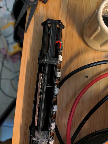
So I used WLED on an ESP32, that barely fit into the tube, and an I2S MEMS mic on a small board that sits above the top of ESP32 near the top of the tube.

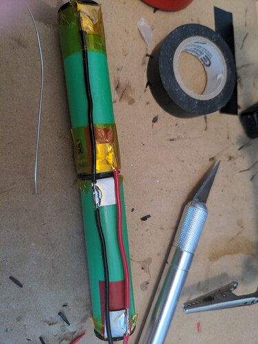
So, here’s soldering the 20awg solid core wire along the tabs. I covered the ends with kaptan tape and put a 1mm 3D printed cap between cells for additional protection. Then I covered it all with heat shrink.

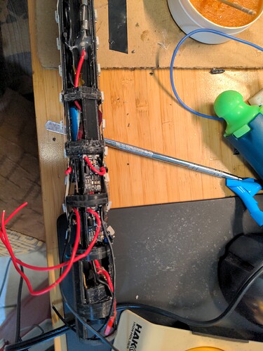
This is the end with the 6x1a boost modules up to 5v, and the little bit at the top is the back of the holder for the BMS, with the 10a fast blow wired wired in to the input/output line. Then below that, at the very bottom, is the on/off switch and JST-RCY charging connector. JST-RCY is good for 3a, and my CC/CV charger is setup for 2a, so I’m good.

The ESP32 is powered by pulling 5v off of 1 of the LED strips, and then the LED strips are wired in series so I essentially have 1 single long strip, which WLED lets me set it up into distinct segments, so it appears that they’re all in parallel, but I can end up treating it as a 2D matrix. It’s a bit fragile, seems like it’ll keep working for now. Not sure if I’ll do a v2 for next year, or just keep it as is. Because it was a PITA to get it down into the tube, just a tiiiiiny bit tight. Really need to get the tube ID a few mm wider. Maybe just make it a thinner wall, rather than overall wider tube. There’s a plastics shop not far from me, so maybe I’ll be able to get the tube replaced, but keep the cool transparent handle. Unfortunately I forgot to put an extra LED or two pointing straight up into the handle.

And here’s a short video of it going with some music.

Something I also found in the WLED-SR (Sound Reactive) branch has an audio sync, so I can have one device’s mic provide the audio out over a local AP that it hosts to the other devices in my coat/hat/cane, along with telling the others when it shifts the playlist of effects or what not.

Looks like it’ll use 1.5-2W/hr, so with 7 of the 2250mAh cells, I should have plenty to last through the night and still be able to charge up fully during the day.

I’m fairly certain I need one of these now… Nice build!

I’d rate it as decent, and many lessons learned in terms of when I started to try and fit it in, and started having to force things, I should have backed off and pulled it, at least partially, apart and rebuilt it. Like I said, a good v1, but lots of room for build improvement. And being able to actually extract it without probably 1/2 tearing it apart (mostly 3D printed bits, and some soldered connections on the LED strips, and the 1 pixel I had to splice in because I sheared it off the strip trying to force it in…) getting it extracted.

Ideally a tube with inner diameter 2-5mm wider, and perhaps frosted would be nice to give a bit of diffusion to the individual pixels. Which may mean I could go for 30/m instead of 60m, even needing to drive them to somewhat higher brightness (currently near minimum), which would save a lot of power as well.

Probably end up getting a less-than-awesome-but-cheaper-and-good-enough spot welder to tab cells so Pos and Neg goes 180-deg from each other, or at a minimum line them up more evenly with each other. That was actually some of the problems, is the tabs weren’t on quite square to each other, so the connecting wire had to ‘wander’ a bit. I also have 1 continuous run of wire, where I used an Xacto knife to strip of insulation in the middle of the wire to solder onto the tabs. Not sure that I really needed to do that.

I do wonder if I could have used a spot welder to tack weld the wire in place given that it’s solid core, then add some solder. shrug

Biggest thing though, is internal diameter. With the wires and heat shrink the battery is a bit wider than I expected, enough that it caused major problems, combined with the height of the pixels on the strips. Maybe 17500 cells, or even 14500 instead to give me more room. Hmm…apparently there’s a 16650 size cells, although it’s rare, but still fairly high capacity can be found. I found in practice, I can run the brightness almost at the minimum and it’s plenty bright, and not all 3 colors will be on on all of the pixels at the same time, unless I specifically pick solid color mode and force it. Especially not with the music reactive modes, lots of pixels pulsing on and off and different colors, so actual power usage per strip is a lot lower than I expected. In theory, each pixel is 0.3W peak, with 44 pixels per strip that’s 13.2W/~2.6A, which is WAAAAY over what the little boost boards (1A@5v) are rated for, and even then I’d prefer no more than 0.7-0.8a continuous. However, in practice with the ESP board on one of the strips, it would pulse up to 0.7-0.8a, but that was peaks, and generally 0.4-0.5. And that was at ~1/2 brightness, not nearly minimum like I decided I’ll be able to use.

So to sum that all up, I expect I’ll need a lot less total power than I thought I’d need. I expect I’ll use 40-50Wh assuming it’s on for a full 8hrs, might even be a fair bit less.

Next up, is my faux fur coat. Going to have 2 strips in parallel (30/m) of RGBW (neutral white), and 3 or 4 strips in parallel, probably double sided, for the collar for when it’s up or flat. By my estimate with the doubled strips I’ll need 10+m of strips. Good thing I got 4x5m rolls. Planning ahead! And I’ve got some ideas for the rest of the LEDs for lighting up our new sign that we’ll have.

EDIT: And you can always build a Sound Reactive one yourself pretty easily. ESP32 + firmware, and a MEMS I2C mic is pretty easy to hook up and better quality than an analog mic (although that’s supported too).