DIY Hardware: Documenting YARH Device Builds

Recently, my ongoing dreams of being able to repair, make or modify every tool and gadget around me met with my goals of abandoning as much proprietary software and hardware as possible by discovery of the yarh.io project. Aka [Y]ET [A]NOTHER [R]ASPBERRY [H]ANDHELD.

It’s a project to make hackable raspberry pi 3 devices in 3D printed housings. I don’t know what ‘another’ handhelds they’re referring to because I’ve seen few others beyond retro-pi gaming handhelds and I think this is by far the most mature project I’ve seen yet.

It is still like most open source projects in that it’s documentation is a bit lacking. CAD files are not available, only the .STLs. Code for the Arduino pro micro in the MK2 seems completely missing. So some parts of this project are likely to be a bit open to personal interpretation.

So, here’s the start of an ongoing build log of putting some together and seeing what they can do. Some initial hardware is ordered, including some more filament spools. I figured to start printing the MK2, but it seems worth playing with both and seeing what features and form factors work best.

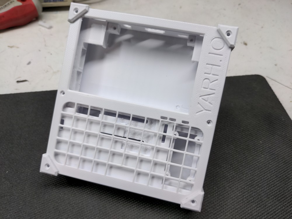
Here’s all the parts for the first one:

Everything fits together very well. I seem to lack the right size 2-56 screws to put it together, so those are on order. Here is a test fitup:

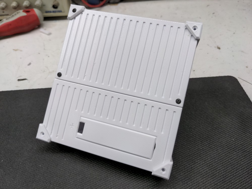
These will be more visually distinct in the near future, as I plan on printing parts in different colors for more interest. Personally, I quite like the color scheme of devices found in the
Subnautica universe, so this will probably get a mix of grey and orange parts added on to it. Some prefer all black and more power to them. I can print those as soon as my new spools arrive.

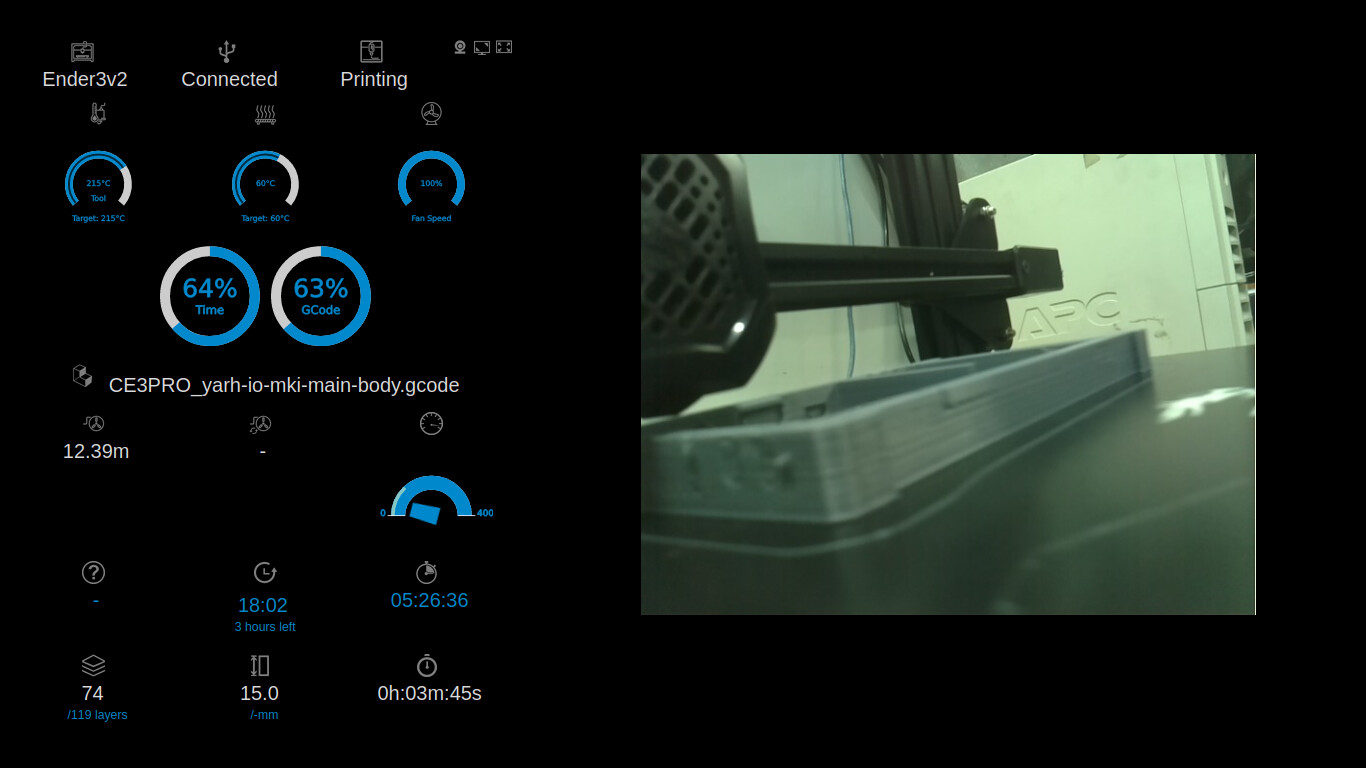
As I type the backplate for the MK1 is printing, and I can give a first impression of the difference in feel between the two. Just looking at the hardware, it looks like the Pimoroni ‘Hyperpixel’ display of the MK2 will be superior in it’s contrast, resolution, and capacitive touchscreen. The MK1 on the other hand has a track pad, and since the HDMI display doesn’t consume all the GPIO pins, there is room and breakouts leading into the keyboard compartment for internal expansions.

The MK2 would be limited to USB devices for the most part, but I look forward to seeing what kind of brainstorming happens hear on that end. A USB sound card might run Fldigi and radio CAT control passably well. I myself want some kind of LoRa modem, likely something as found from the nice fellow at unsigned.io

I recently realized one of my frustrations with the Pi are the terrible connectors. Sure, USB-A is convenient, but not if you want to mount the Pi inside a case with some other stuff (like a HDD, Various USB dongles, etc).

Second, USB connectors don’t stand up to vibration well (i.e. I want to mount one on my bicycle). I’ve been using 20AHr USB phone packs on my bicycle to power accessories, and the USB-A connectors only last about 1-2 yrs (that’s only 50-100 round trips to work!) before the vibration kills them.

Lastly, Also USB-A connectors are huge. You add about 2" to the size (length) of the board if you add USB connectors. Yes, there are angled ones, but they’re still bulky and not vibration resistant.

Why not make boards with pin headers? Or empty pads to add your own? Regular desktop cases come with bulkhead mount connectors with wire harnesses ending in pin headers. For example 1x5 0.1" header is standard on motherboard USB2 connectors, or 2x5 for dual USB2. USB-C with 20 pins is bulky but possible. 2mm JST headers are super compact and readily available.

Ethernet is difficult due to signal integrity issues (100BT runs at 31 MHz, 1000BT runs at 62.5 MHz), but those connectors are smaller and F-F Ethernet keystones are pretty inexpensive.

So… I guess I need to find someone who makes a CM4 carrier board that has connector harnesses so they’re more space friendly. That seems to be the route that the more compact Pi handhelds are heading in.

Hm, the RPi 4 appears to use thru-hole usb sockets. That makes a tiny pcb adapter to regular 0.1" headers possible! (for USB2 at least).

1 Like

I feel your pain about the USB connectors. I’d also like to take this opportunity to whine about the RJ series of connectors. All your data integrity hanging on one, tiny, crappy plastic tab. Every amateur radio mobile built in the last 20 years has the handset connected via RJ45. I think I speak for everyone who’s ever snagged a handset on something when I say: WWWHHHHYYYY!?!?!

1 Like

If USB A doesn’t last and RJ45 is inconvenient, what sort of connectors do you like?

Boats are worse. I’ve had boat vibration/slamming knock out mini/micro-USB connectors in < 6 months at sea. The problem there is fretting - the plating gets worn away quickly, then the bare copper is exposed and corrodes almost immediately in the humidity. If the matching pins aren’t copper (sometimes they’re tin plate, or something else) then you also get galvanic corrosion. USB-A was by far longer-lasting, if only because the connector surface area was larger.

The solution, which I learned later, is to use a microfilm coating like Deoxit-G (for gold) - this lubricates the connection so that there is zero actual metal-on-metal contact and instead everything slides on a one- or two-atoms-thick layer of polymer. At skin thicknesses that thin, the normally dielectric polymer conducts perfectly well. The connections last impressively long under some terrible conditions when properly coated NEW (e.g. this won’t restore damaged connectors) before putting in service the first time.

That said, they also make circular locking housings for USB, Ethernet, and other normal connectors which physically force the mating surfaces against each other and prohibit mechanical vibration. These are used quite often on powerboats which use a lot of high-tech electronics in the nav systems but are all interconnected by RJ-45 for the most part. For USB-2.0 you can also use mil-spec circular connectors if you’re careful with how you wire them, but since they don’t preserve the twists properly you cannot use them for USB-3.0 to my knowledge.

DB9 connectors, or the various sizes and pin counts of ‘aviation connector’ like this:

My HF rig uses that connector. Many older radios, even some CB gear uses that or a similar round thread-together connector. Threaded or bayonet-style connections holding the parts together. Larger surface area between pin and socket. Crimp and/or solderability between the pins and the cable inside the connector.

I’d even prefer DIN connectors for most applications, although I have had to solder a few 8+ pin versions before and that wasn’t fun.

1 Like

MK1 housing parts still printing…