Installation review: Siemens FS140 whole house surge protector

Among other things to kick off the endless freak show that was 2020, along about March a spring thunderstorm came along that nailed a power line just down the street from my house. I was home at the time. That was one really big boom, and an instant blinding flash of light coming in every window.

First discovery was that the fuse disconnect from the power pole to the ground-mount transformer had blown. I never saw any broken trees or char-marks on the ground, but the strike must have been close.

IMG_20200430_172625

After power was restored the second discovery was the death of about $150 in computer equipment. An old HDTV monitor, one cheap graphics card (just the card, not the PC. go figure), and two network switches. All of which were attached to various UPSā€™s at the time.

So here we are one year later and the spring thunderstorms are starting up again. I decided itā€™s time to add more protection to things, but Iā€™m glad I didnā€™t get around to this until reading the Polyphaser book mentioned elsewhere.

Why Iā€™m convinced whole-house surge suppressors are the way to go

There are three primary types of surge suppression device in use today: The metal-oxide varistor [MOV], the gas-discharge tube, and so-called ā€˜activeā€™ silicon devices (usually SCRā€™s and the like).

The MOV is the default in just about every plug-in surge suppressor on the market. The MOVā€™s resistance decreases with applied voltage, and can do so with a reasonably fast response time usually limited by the lead inductance more than the device itself.

The biggest downside to MOVā€™s is the fact that smaller surges can kill them slowly. They die a little bit every time they conduct to ground. Itā€™s common to find in the American south-east a surge protector that failed to protect connected equipment from a major surge, primarily because the unit has been hit by years of smaller, un-noticed surges that reduced the MOVā€™s effectiveness until the big one came.

The gas-discharge tube is a physical gap between two electrodes between a line and ground, filled with a gas and spaced such to have a very specific voltage breakdown, above which the tube will short the excessive voltage to ground. Itā€™s response time to a surge is higher than an MOV, but they will last just about forever. They are most common on lines that do not carry high current, such as telephone/ethernet lines and coax cables.

Protection device number 3 is what seems to be referred to under the broad category of ā€˜active siliconā€™. I gather this is primarily some combination of SCRā€™s, Triacs, or SADā€™s [silicon avalanche diode], but whole-house SPD manufacturers donā€™t seem to want to post schematics of whatā€™s inside the un-openable boxes.

This is the common method for surge protection that handles both high surge currents, and deals with ā€˜whole-houseā€™ or similar protection of an entire breaker panel. Advantages are response times as-fast or faster than MOVā€™s, they will survive repeated smaller surges and still survive, and maybe most importantly they can cover a fault-type not covered by other surge devices.

Line-to-line faults

While rarer than a typical ā€˜line-to-groundā€™ fault, line-to-line faults can occur if a surge arrives near the precise moment the AC voltages are at their peak- in the USA at least, that would mean each line is near +/- 170V respectively. This is a point where the lowest impedance path the lightning strike sees can be between the hot wires instead of from a hot line to ground or bonded neutral. The resulting damage to down-line equipment can be the same, and if it happens near the outlet your computer is plugged into a typical MOV surge suppressor wonā€™t be able to do anything about it.

Well enough rambling about the whyā€™s, hereā€™s what I did about it:

The Siemens FS140 SPD

IMG_20210404_152933

While there are certainly much cheaper SPDā€™s on the market, protective equipment isnā€™t something where ā€˜good enoughā€™ is a phrase I want to hear. If I feel itā€™s worth doing to protect expensive equipment, itā€™s worth doing right. Enter the FS140.

There are 3 models available, in 60kA, 100kA, and 140kA ratings. Some of the marketing literature listed those ratings in order of ā€˜house sizeā€™ā€¦ which is bizzare. The surge coming into the building is or is not greater than the deviceā€™s rating. None of which has anything to do with your house size. Well anywayā€¦

So I bought the 140kA rated version for $178. One of the highest-rated (and most expensive) universal SPDā€™s I could find. It compatible with any power panel, as it mounts externally and requires wiring to a dedicated 20-amp 2-pole breaker (as close to the main breaker as possible).

A flush-mount kit is available if you want it in a wall, although you should make sure the front is inspect-able to view the LED indicators. It is also an outdoor rated enclosure, should it need to go outside at a disconnect. Iā€™d probably build it a little roof to protect it from UV exposure anyway.

This first one is going in my shop, which has a separate meter/service entrance than the house. The house will get one too, but that will come later as Iā€™m unwilling to deal with the in-wall rats-nest of wiring and nonsense Iā€™ll have to sort through to get it in there.

So hereā€™s the quick install

If youā€™re qualified to work in a breaker panel or install an outlet, you can install this thing. Itā€™s nothing special. (and if you arnā€™t qualified well, go find someone who is.)

IMG_20210406_082640

Plenty of room here, so weā€™ll put this breaker in the upper right space. Upper left is saved for a generator inlet that Iā€™ll get to eventually.

The shorter the wiring to the SPD, the better. Do not add wire nuts to this. I know, this isnā€™t a cad-welded ground connection like you might see on a cell-tower but still, connections are the most likely point to fail during a lightning strike so donā€™t add any.

Iā€™ll put this in the lower right of the panel with a short 3/4 rigid conduit nipple. Thatā€™s about half way from the breaker in the upper right to the ground/neutral bars on the left side of the panel.

IMG_20210406_083140

Marking wires with sharpie and electrical tape works ok, but now Iā€™ve got this fancy label maker and an excuse to use it.

IMG_20210406_083532

Thatā€™s right- printable heat-shrink tubing!

IMG_20210406_090030

I should have gotten another inside shot before I buttoned it up, but it was dark at the timeā€¦

Here it is online:

IMG_20210406_090116

Green is all-good. A red light and alarm will turn on if it detects either a ground-neutral bond fault or (most importantly) if itā€™s been killed by a significant surge and no longer operable.

So Iā€™m feeling good about this install. Canā€™t review if it protects from surges or not yet, obviously. Not willing to go outside with a kite next rain-storm, but so far so good.
1 Like

Grammar/spelling issue, I think

I think you mean ā€œtheir areā€.

Otherwise, something that I think Iā€™ll keep in mind whenever I end up owning something!

Is there any kind of super-cap for very transient/temporary brownout/low voltage? Like a fridge or A/C compressor startup kind of situation. Iā€™ve actually noticed my under cabinet LED strip lighting occasionally starts showing some flickering for a few moments, whereas normally I canā€™t see the PWM at all. Iā€™m guess itā€™s some kind of low-voltage for a moment. Iā€™m thinking I might just inject a moderate sized capacitor on the +12v input. Iā€™m curious if youā€™ve encountered anything similar for whole house in your investigations though, and if it might be worth it or not.

Oops, yup, typo. Although I think it is still ā€˜there areā€™ right? Was typing fast. Took me longer to do the writeup than it did to install the thing actually.

There is such a thing as ā€˜panel levelā€™ EMI filtering, although I donā€™t believe that would handle anything considered a brownout. Possibly the ringing that occurs when a large load is connected or disconnected by a switch, but ā€˜hundreds of milliseconds or moreā€™ time periods of low voltage would typically have to generate a voltage from somewhere, such as with a ā€˜line interactiveā€™ UPS. Thatā€™s not for an entire house though.

Even in industrial settings, if youā€™ve got EMI or voltage-sag problems, thatā€™s usually treated at the device causing the problem, not the entire panel. For a large HVAC compressor or even 10HP+ air-compressor that would usually be the job of a ā€˜soft-starterā€™, or a VFD which usually also have soft-start capabilities.

In your case filtering the lights is probably the simple option. You might want some kind of LC circuit in there, the added inductor will help deal with noise beyond what just the capacitor will make up for.

More high-frequency noise than voltage sag I think though. I had that problem on a DC motor controller I built. ~100khz noise from the motors with a +/-6v peak at least would make it back onto the 12v power rail, right over several large filter caps and even through the 5v linear regulator, causing brownout-detector resets of the MCU whenever the noise pulled the voltage down below ~3v.

Ah, so you wouldnā€™t generally have large enough capacitors without crazy expense to handle transient voltage drops throughout the home, youā€™d at most do EMI/RFI filtering. Or add some kind of UPS with the power to handle a second or two of voltage sag.

Not sure itā€™s noise in the line or not, not sure where itā€™s coming from. My theory was voltage sag, but then again Iā€™ve got an AC->DC in there to get the 12v. So Iā€™d have figured itā€™d handle ā€œlowā€ voltage fine from the 110v, just pull a few milli-amp more as part of the process. Whereas noiseā€¦yeah, noise could possibly getting through.

Iā€™m not too familiar with these sorts of electronics bits at all. Just take a electrolytic capacitor and stick it on V+?

Yeah most large-scale systems are designed with the expectation that the grid power supplying it will be kept to a pretty tight standard. Thatā€™s why itā€™s such a big deal when the frequency drifts by even tenths of hertz.

Without a power supply schematic, or an oscilloscope on the power rail itā€™d be hard to say for sure. Noise is most likely, unless the power supply is unbelievably cheap. Noise is a likely culprit, because the regulation of the 12vdc supply should indeed continue to provide 12v even if the input drops by tens of volts. Most modern switching supplies can handle pretty wide input ranges, assuming theyā€™re constant.

I havenā€™t looked at the AC side of my desk to see whatā€™s up, but Iā€™ve got a solder and hot-air station unit on my desk, and some LED tape overhead with a homemade PWM dimmer circuit and a 12v wallwart I had lying around. The solder iron works fine, but when I turn the hot-air gun on the LEDs flicker quite a bit.

Anyway, no harm in trying an electrolytic capacitor between Vdc+ and ground. If itā€™s a brief dimming when something else in the house powers on, it will probably help. If itā€™s a constant flicker while the thing is running, it probably wonā€™t help as much.

Do you know if the ā€œhalf size/pairedā€ breakers are acceptable for surge protector installations? I wouldnā€™t mind putting one on the house, though the Midnite solar ones are MOV based. They claim the status LED goes out if the MOVs are fried.

I should get around to putting them on the solar boxes some nightā€¦

So it is a cheapo 12v PSU from Amazon, so Iā€™m not holding out much hope that itā€™s especially good. Just decent enough and for cheap.

So what it is is a temporary flickering. Like the PWM rate drops low enough I can see it. Rather than the normal which is I canā€™t see any PWM at all, just a smooth dimmer/brighter.

And you mean put a electrolytic cap cross the input +/- wires? I thought itā€™d just be inline on the V+.

AFAIK, no. A tandem breaker simply jams two separate 110v circuit breakers into one space, giving you two separate 110v only circuits. An SPD needs a 220v connection, one hot wire to each leg in the panel. If there is such a thing as a tandem breaker than reaches both hot-sides of the panel, itā€™s a panel/breaker style Iā€™ve never encountered before.

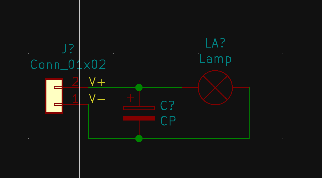
Between V+ and V-, on the DC output of the supply. Like this:

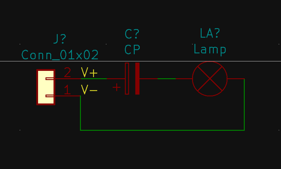
ā€˜inlineā€™ to me implies the device is in series, like this:

ā€¦and that wonā€™t help because a capacitor blocks DC. The schematic in the second picture will prevent all current from reaching the lamp.

Also, donā€™t ever install an electrolytic capacitor backwards. Been there, done that, got the stained underpants. (Yes, installing an electrolytic backwards under DC bias can make them explode).

Ah rightā€¦electrolytic has a bias. Soā€¦Lamp in this case is the Load? So between the DC PSU and the input to the device, put the capacitor across V+ and V-. The Load is the ESP device, which then switches the MOSFETs for the PWM on each individual LED line.

EDIT: Hmmā€¦thatā€™s even easier to do, the V+/V- are screw terminals. Just unplug from the power source, pop the lid off, carefully unscrew, slide in the legs (might need to trim), and screw back down.

They exist. Typically youā€™ve got inner and outer cross ties, or only inner.

That will work. Iā€™d probably start with something like a 470uF cap to start and see if that does anything, but it might take something bigger.

Quad-tandem breakers? Hadnā€™t seen those before, neat! Iā€™m going to go see if thereā€™s any available for the main panel in the house, that would solve one of the big problems for getting an SPD on that panel.