So I’m trying to take Lumazoid: realtime music visualizer board for LED strips (all PCB, specs, firmware FOSS) and re-work it to be a much smaller, slimmer board so I can fit it into a small place. I’m using EasyEDA for design, and planning on JLCPCB for PCB and they offer SMD/SMT assembly, yay!
However, the oscillator/crystal that they use, which I found on the JLCPCB site, is out of stock. Specifically this one. So I don’t know enough about design/PCB/microcontrollers to figure out an alternative 16MHz crystal, if it has a different pinout, to slot in.
So, HALP. I figure this would be a good place to find those who know a lot more about it than I do.
That’s a 16MHz 18pF 50 Ohm SMD crystal. I don’t know how picky that particular design is for things like ESR and capacitive loading. If you’re using a microchip with a built-in RC oscillator you might be able to skip the crystal entirely. I recommend doing so for simple projects like this anyway, fewer parts, fewer things to go wrong. I don’t know if the 328p has one to use or not, but I assume not as those are pretty simple uCs. In any case, they’re loading it with 22pF per leg in parallel with whatever the chip loading is and coming up with 18pF, which, since you won’t get less than 22pF out of parallel capacitance, indicates that either I am clueless about how oscillator loading is actually calculated or that it doesn’t matter very much and you can probably choose a variety of values from a bit less to probably quite a bit more than 18pF and be fine (I would buy a stack of loading capacitors to tune it ranging from 7pF up to about 30 in 3-5pF steps if you really care - most designs are fine-tuned this way after initial production anyway - the board and chip loading cannot be perfectly calculated up front).
So start looking for a 16MHz crystal in the 50ohm-ish ESR range (probably 25 to 100 is fine, but you might read the 328p tech manual or other tech notes to be sure) that’s got a loading capacitance of between 12 and 30 pF and see if any of those are available. If so, get ye the thing and just do what I recommend above and swap out the loading caps (symmetrically) up or down a wee bit if it’s not making you perfectly happy out of the gate.
Edit: Ok, I did a little research because I was curious and it turns out (from this StackExchange article) that the proper equation is Cload = ((C1 * C2) / C1 + C2), in other words, the series capacitance of the two capacitors PLUS the stray capacitance seen by that lead and the input capacitance of the MCU. This implies that they are estimating the input + stray capacitance at around 14pF, so you can adjust the caps to suit another crystal’s loading needs based on that. Now, you’re changing the board and thus the stray capacitance, so I’d still urge you to buy those extra capacitors in case you can’t get the oscillator to start properly with your guesstimate.
It does, but it’s limited to 8Mhz. I don’t know if it matters for audio stuff, but the accuracy of the internal oscillator is generally considered ‘horrible’.
The THT crystals with 22pf caps seem quite robust. I’ve done terrible things with them and had them run solid anyway (atmega and crystal on different breadboards, connected with jumper wires).
Ceramic resonator would probably be fine too if it came to that.
It would matter for audio output, not sure about how much it would matter for parsing, but “horrible” is a good description of the internal oscillator.
Spec is +/- 10%. Most of them are more accurate, but… not by an awful lot. It’s bad enough that if you’re on the edge of spec, serial communication won’t work.
So, for a standalone audio device doing its own A/D/A conversion, clock accuracy is not as important unless you’re interfacing with other digital streams. What matters is jitter and whether or not the frequency varies over time. You can run audio at any sample rate you like - the only thing affected is the nyquist rate and the maths, which need to know what the sample rate is (within a reasonable degree of accuracy depending on your use case). But otherwise if you want to run independently at 38.2kHz, as long as the clock has low jitter and stays at 38.2kHz, your input and output will be perfectly correct if your maths and antialiasing filters are within tolerance to the actual frequency. Granted “within tolerance” is a broad stroke, but for simple applications like this the tolerance is very wide.
So the question I’d have is: is the +/-10% what it varies around (ok, that’s awful) or is it just that you might get 7.2MHz out of it, but rock steady? Either way for this use case yes definitely try to get 16MHz, but do use a crystal if you can and not a ceramic. Ceramics are not great for audio.
As for frequency mattering in this case, it’s more a case of needing 16MHz (or so) to process the samples fast enough to have timely LED reactions, rather than creating any kind of audio, so that’s a big reason why the built-in 8MHz wouldn’t be enough, or what not.
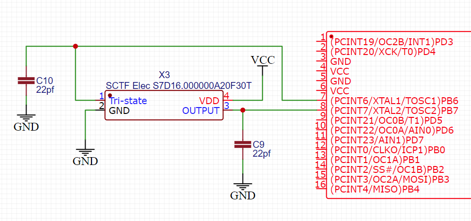
EDIT: So this would be the new circuit setup, does it seem correct?
Somebody who knows the 328p better than I do should chime in, but both of those are powered crystal oscillators, not passive crystals. They have the amplifier built in. What the 328p seems to be wanting is just a crystal, which has symmetric outputs and you load both legs with symmetric capacitance. It has the amplifier inside the chip already, from what I can determine.
I don’t think these are the right sort of chips at all, personally. That said, I don’t know if the 328p has a mode that will permit them to work or not.
Is leaving an empty pad and soldering in the crystal yourself an option? SMT crystals of that size are plenty big to solder with a regular iron, or if you prefer find a footprint with appropriate hole spacing and use a crystal with a THT package.
So just ordered, unfortunately they do minimum of 5 boards. On the other hand, if it all works as I expect/hope, then I can use the other boards in some other bits/projects as well!