Reports From the Manufactory

Well I’ve been posting a fair bit on the 3D printed side of things, but with the printer busy doing some very repetitive parts runs I thought I should start posting up on the metalwork side of things.

So here’s my small shop projects, tips, tricks and demos thread. Anybody feel free to post up your own metal projects and questions too.

So to kick things off, I finally got around to building a mount for my hi-lift jack. If you don’t know the ‘farm-jack’ [or often called by brandname, hilift] is kinda like a radial-arm saw: It will absolutely eat you for lunch if you don’t know what you’re doing, but man when you need it it just does things no other tool can do.

Started by rooting through my box of knob stock.

These aluminum extrusions already have those spline cuts down the outside. They come in very long bars, and I was gifted a bunch of short cutoffs from a company making conveyor systems 2’+ wide with the stuff. They had no need for little 1.5" scraps, but I saw that and thought I have a bunch of threaded knobs I could make with that!

So all I did there was clean up the ends and drill/tap 3/8-16 down the center.

Now here’s some 3"x1/4" HRS bar drilled and marked for bending.

They sell these ‘angle cubes’ for setting up angled cuts on table saws and similar, but I love it to slap on some steel stock in the press brakes.

Much hand pumping the hydraulic press later and we have something bracket shaped.

There seems to be about 4 degrees of spring back in this material. So overbending to about 50 degrees got very, very close to what I needed.

So weld a bolt on the back, prime, paint, and I made some Delrin bumpers for the mount face because why not?

Fits the jack nicely.

1/4" stock was total overkill for this, but it is what was handy. I needed 3" wide, as where I intend to fit this they only work oriented horizontal, so I wanted some more vertical distance between the bolts.

Check back later when I get around to getting this mounted up. It’s going to be some possible over-stressing of rivet-nuts.

1 Like

I have an interesting hardware project in progress I hope to show in a day or so, but here’s one brief setback on that.

I shoulda figured this but didn’t. Don’t drill direct into grade-8 threads!

RIP 11/32 drill.


I did manage to fix this already. Chiseled the broken bit pieces out of there, then plugged a 3/32 carbide end mill down the hole to create a flat spot for the drill to get started on. That kept me from breaking another drill bit. So the drilling, reaming, and pin press-fit can continue.

Except for paint and a couple 5/8" washers I forgot to buy, the articulated hitch project is complete!

Ball-couplers don’t have that much range of motion when off road, and can tend to bottom out in places. Also, this looked like fun to build as an accessory for another trailer project that I hope to have postings of soon.

I didn’t actually make any drawings for this. Just looked at some pictures online and experimented with the bits and pieces I’ve got around.

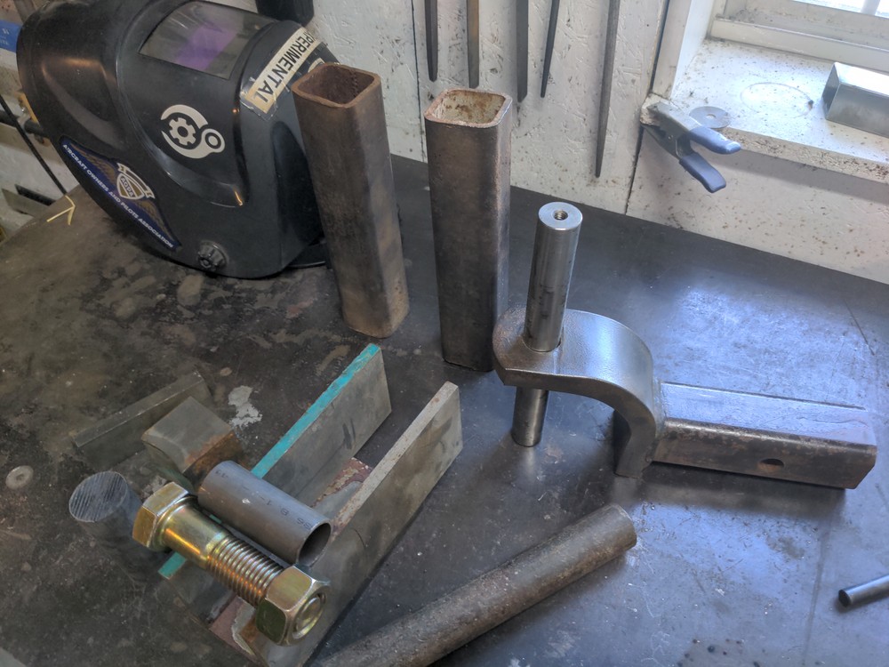
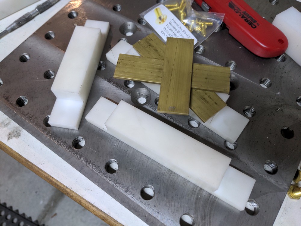
Many designs start by just stacking random stuff together, deciding how everything should fit. This hitch needs 3 separate joints for pitch/yaw/roll; essentially forming a stretched out universal-joint.

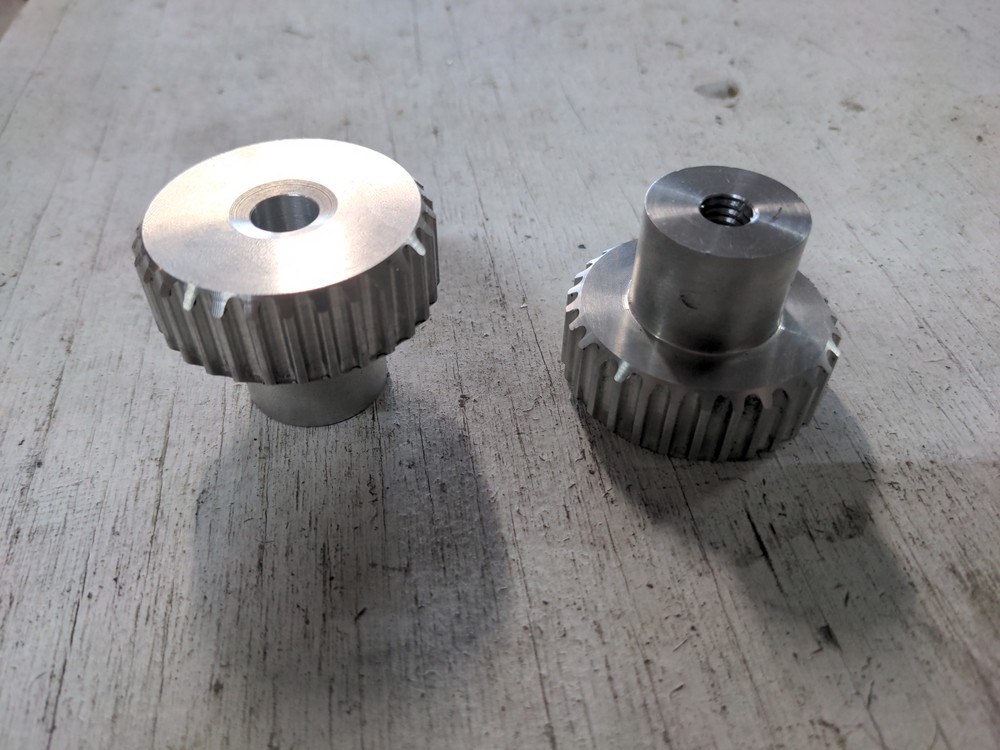
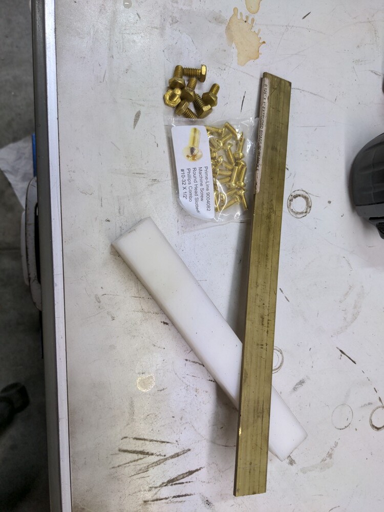
So the roll element will be brought about by this 1"-8 bolt here. Nylon bushings on both sides of a 1/2" plug that gets welded in the end.


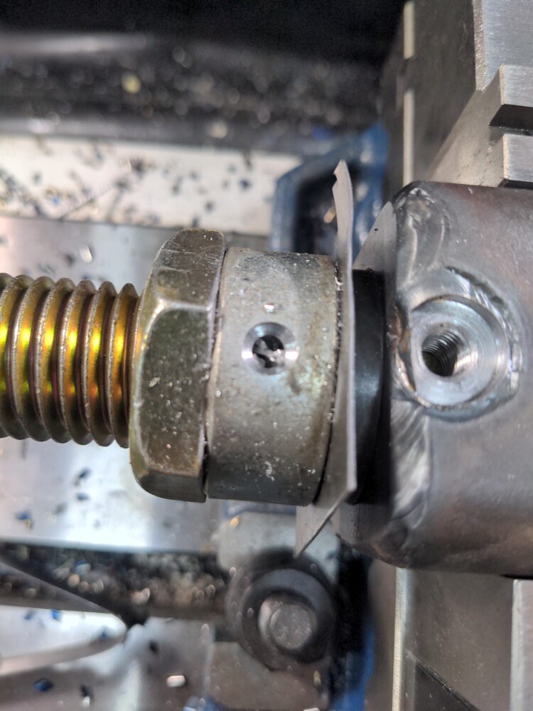
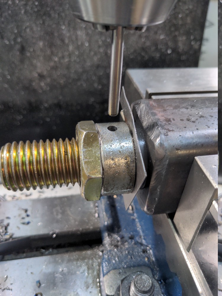
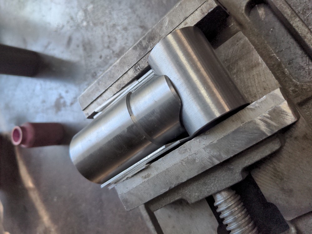
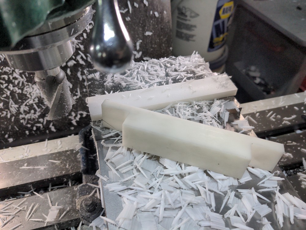
In order for that rotation to happen properly, this bolt gets the hex part removed.

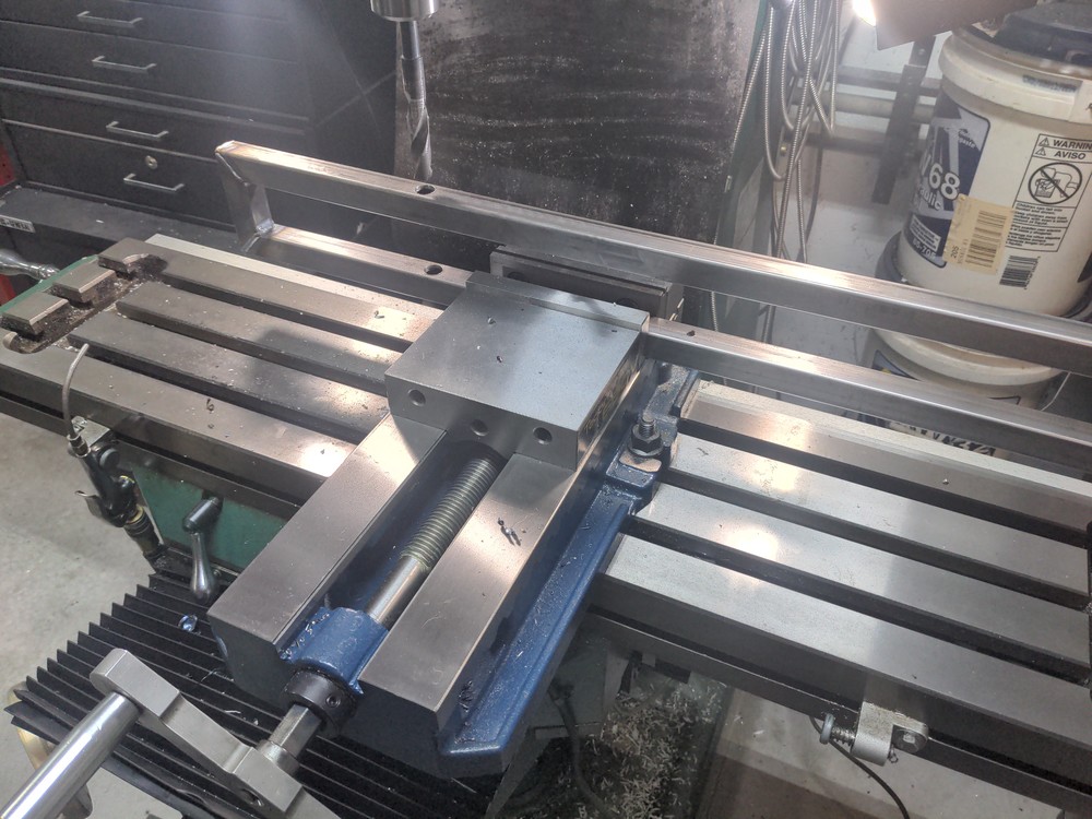
So now I’ve got a stack going through the 2" box tube: Bolt → nylon bushing → plug → nylon bushing → locking collar. I shoved a piece of .030" sheet metal between the collar and nylon bushing, so I could stop the whole thing from turning in the mill, but still have clearance to rotate properly when I took it out.

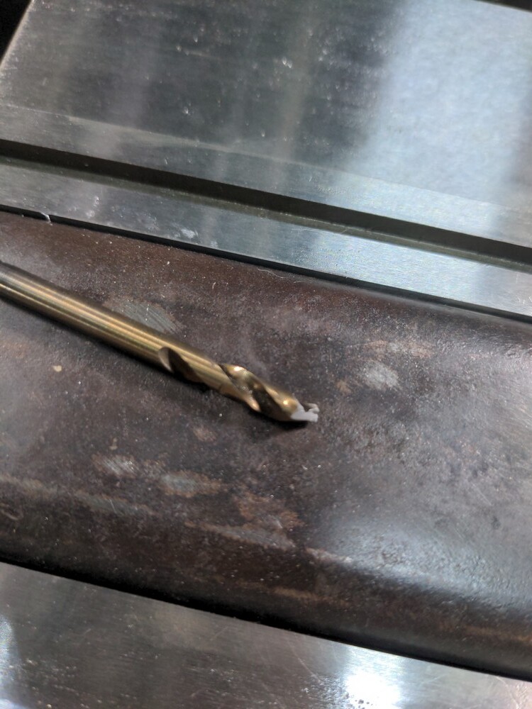
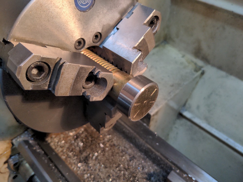
Shop tip: putting long and/or narrow press-fit pins in things can be a pain to get in straight without bending or breaking something. Use a drill chuck should at least get it started, so it’s straight and lined up before taking it to the arbor press [or vise or hammer]

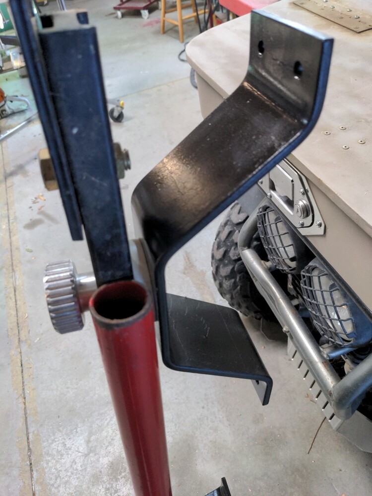
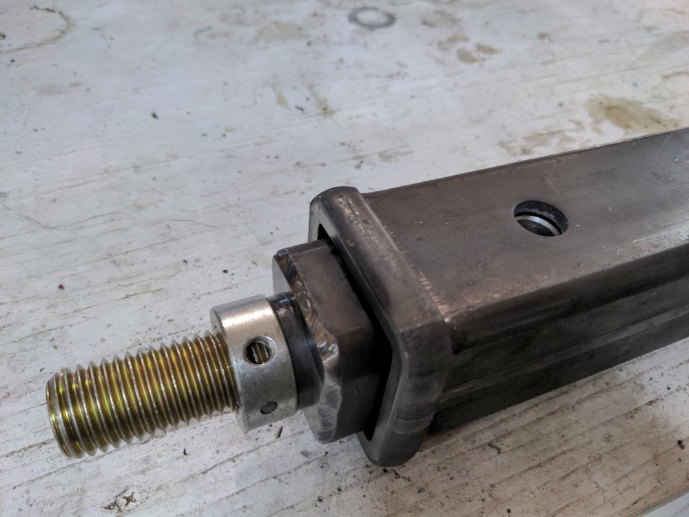
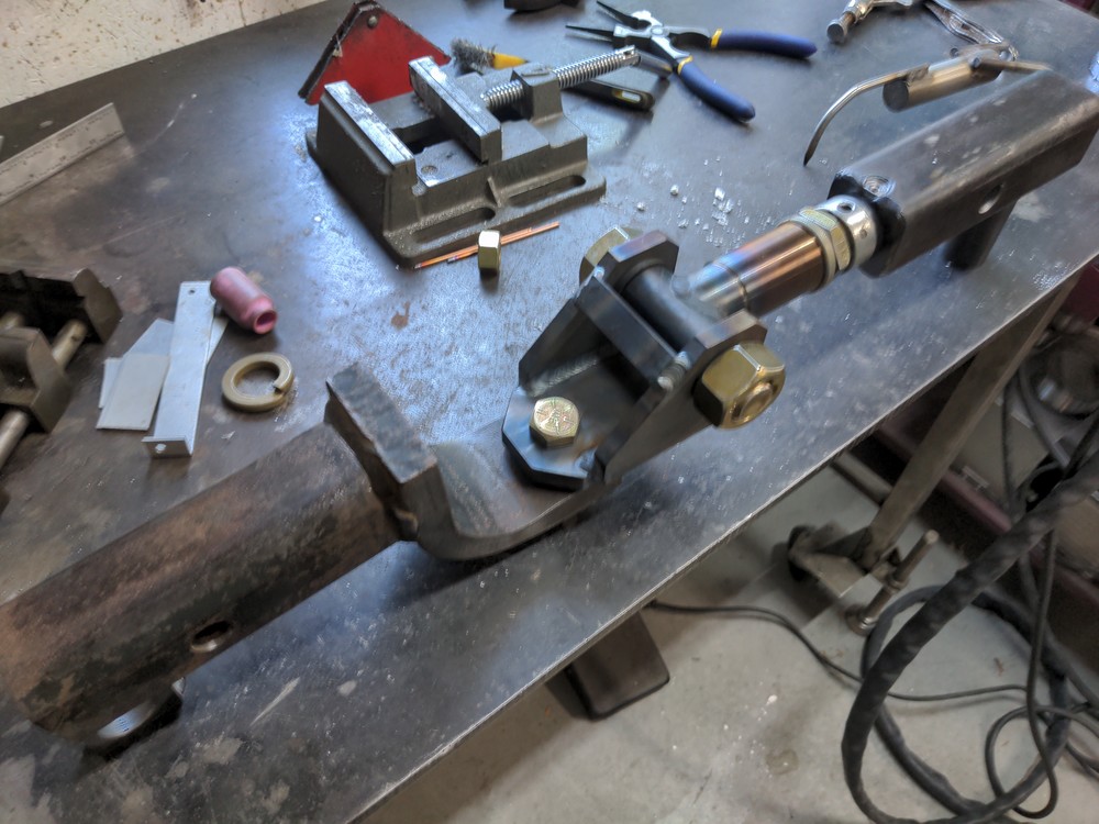
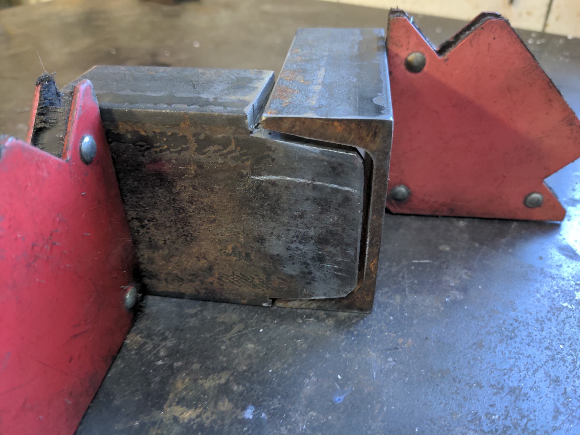
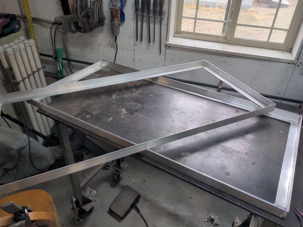
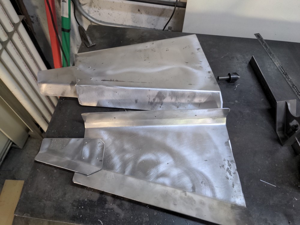
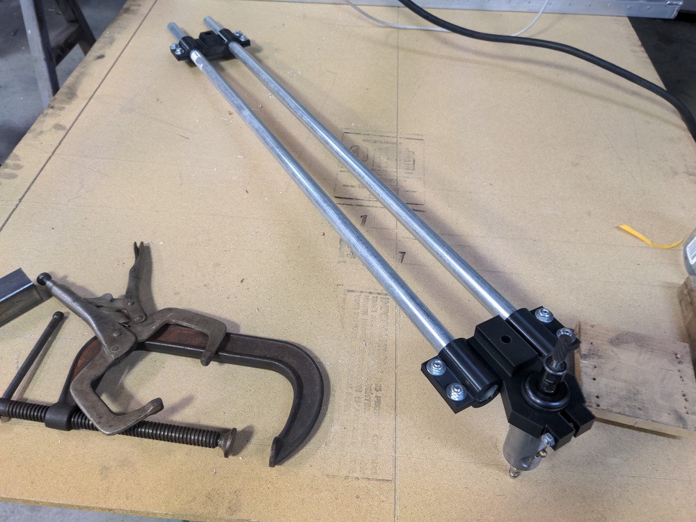
So here’s that test fit into the receiver tube, which will actually be the front of the trailer.

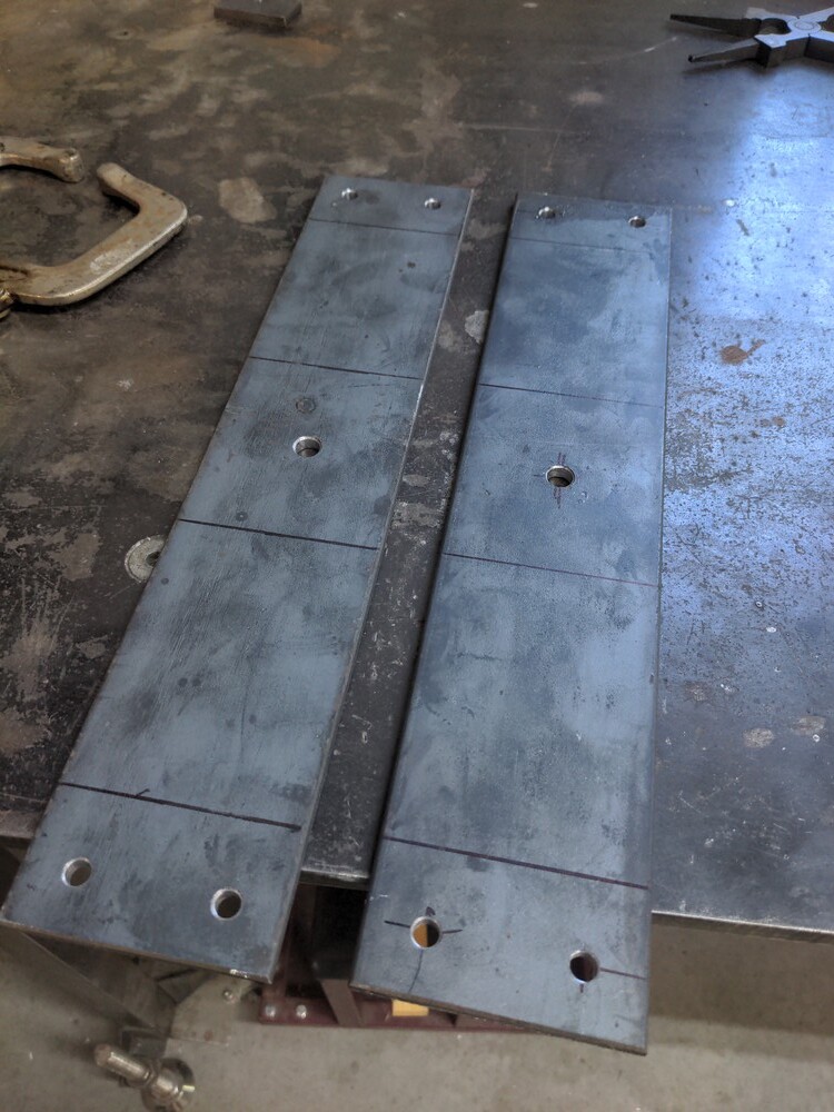
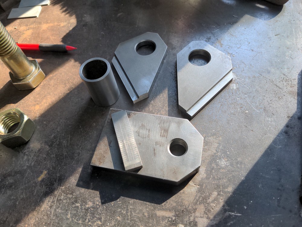
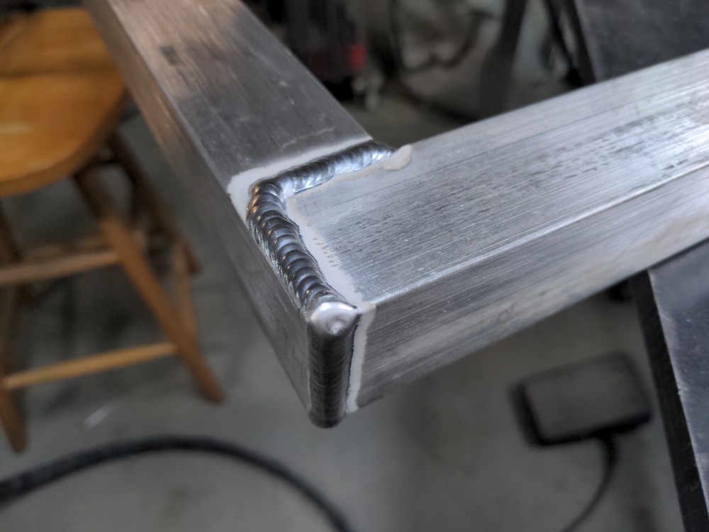
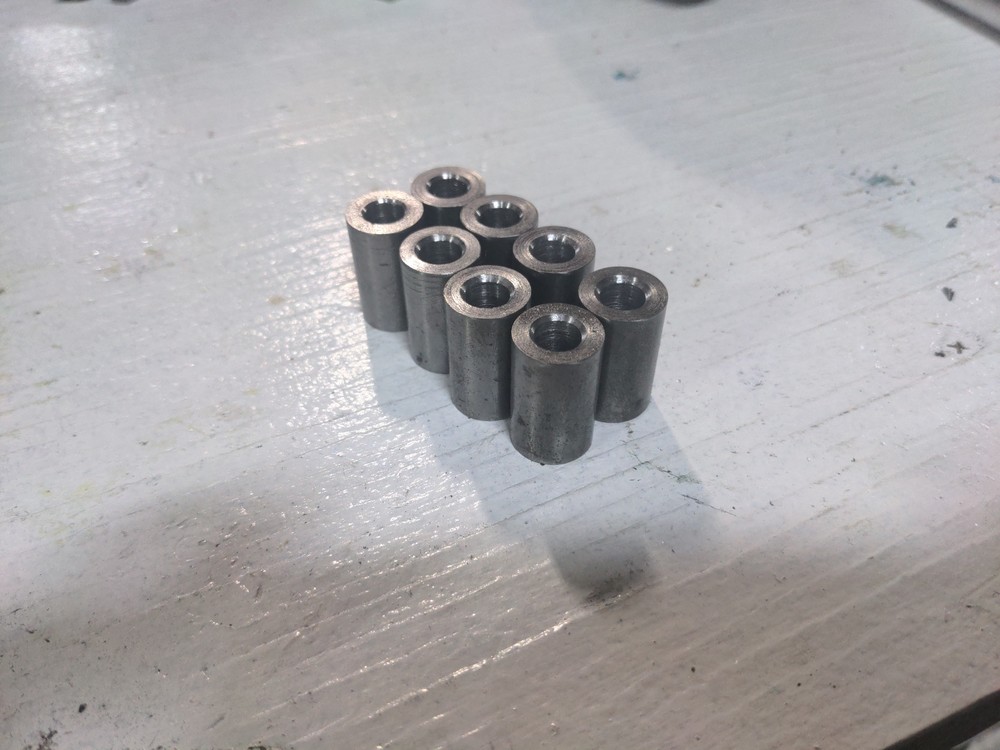
Now for the front half. Clevis parts machined and ready to assemble.

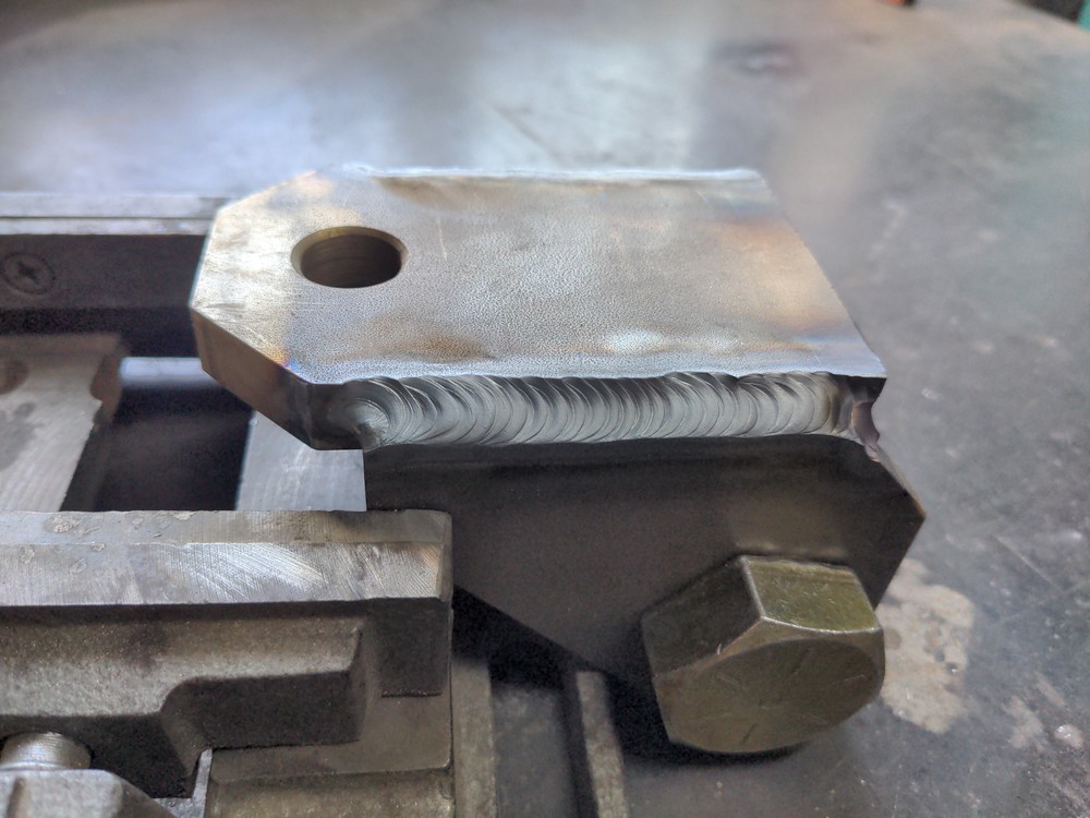
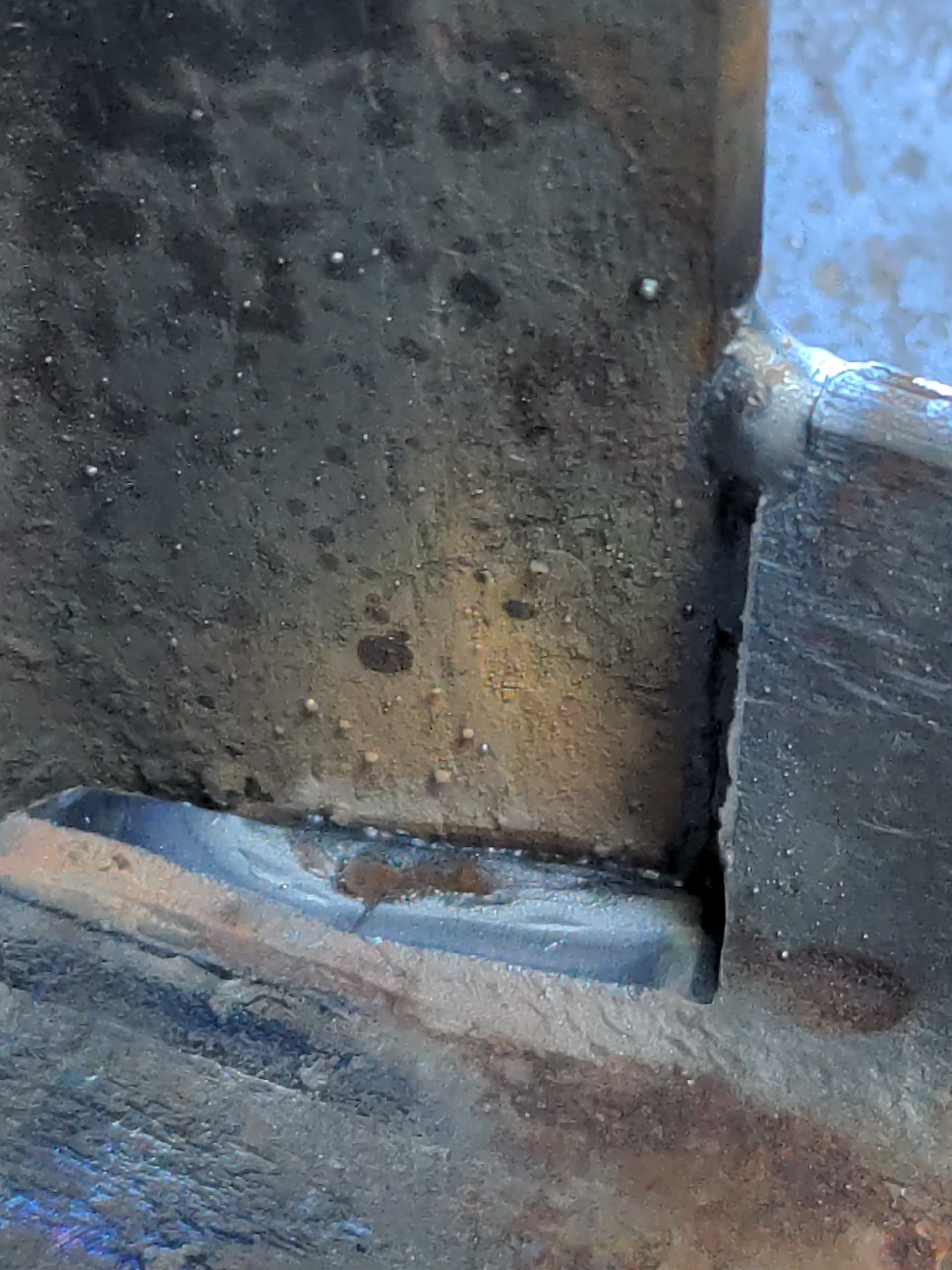
I’d say those welds turned out alright.

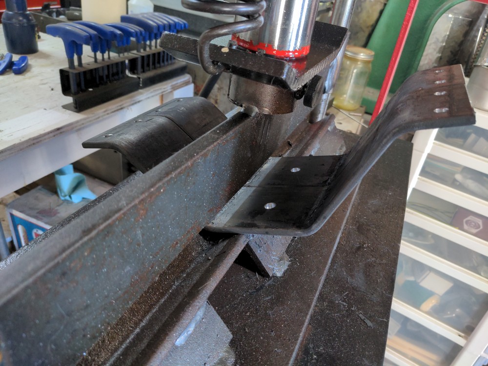
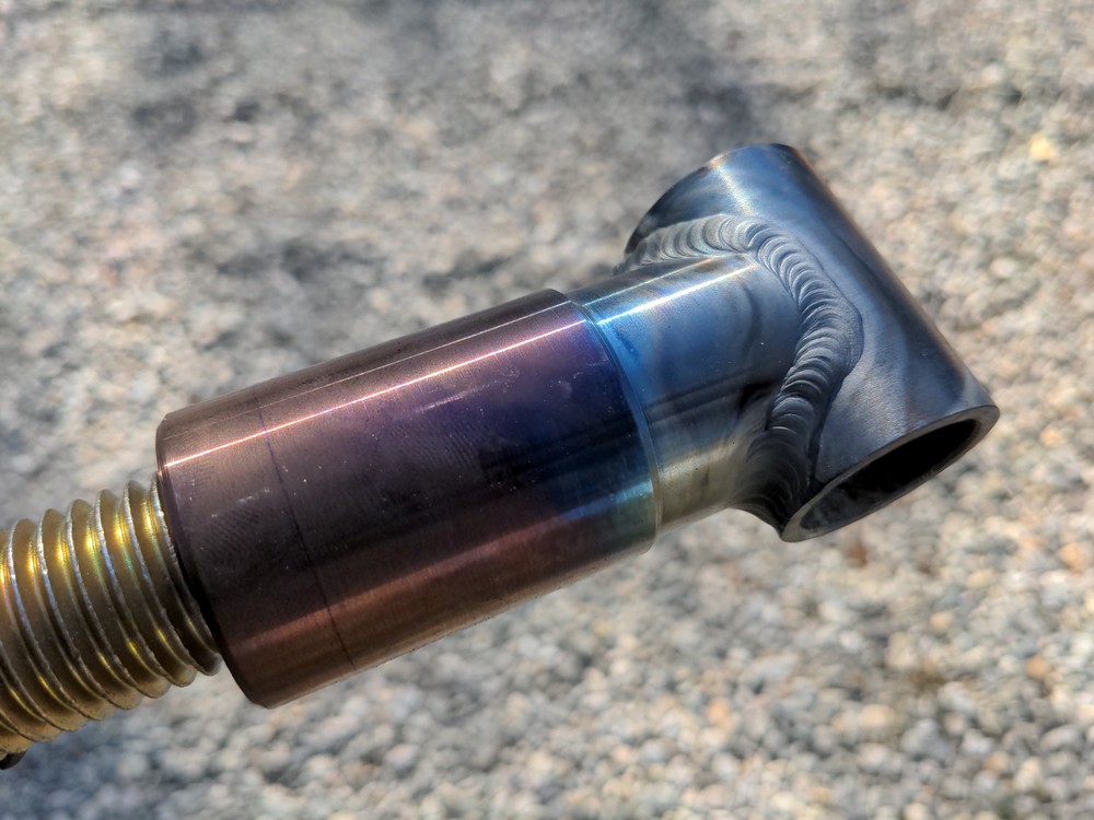
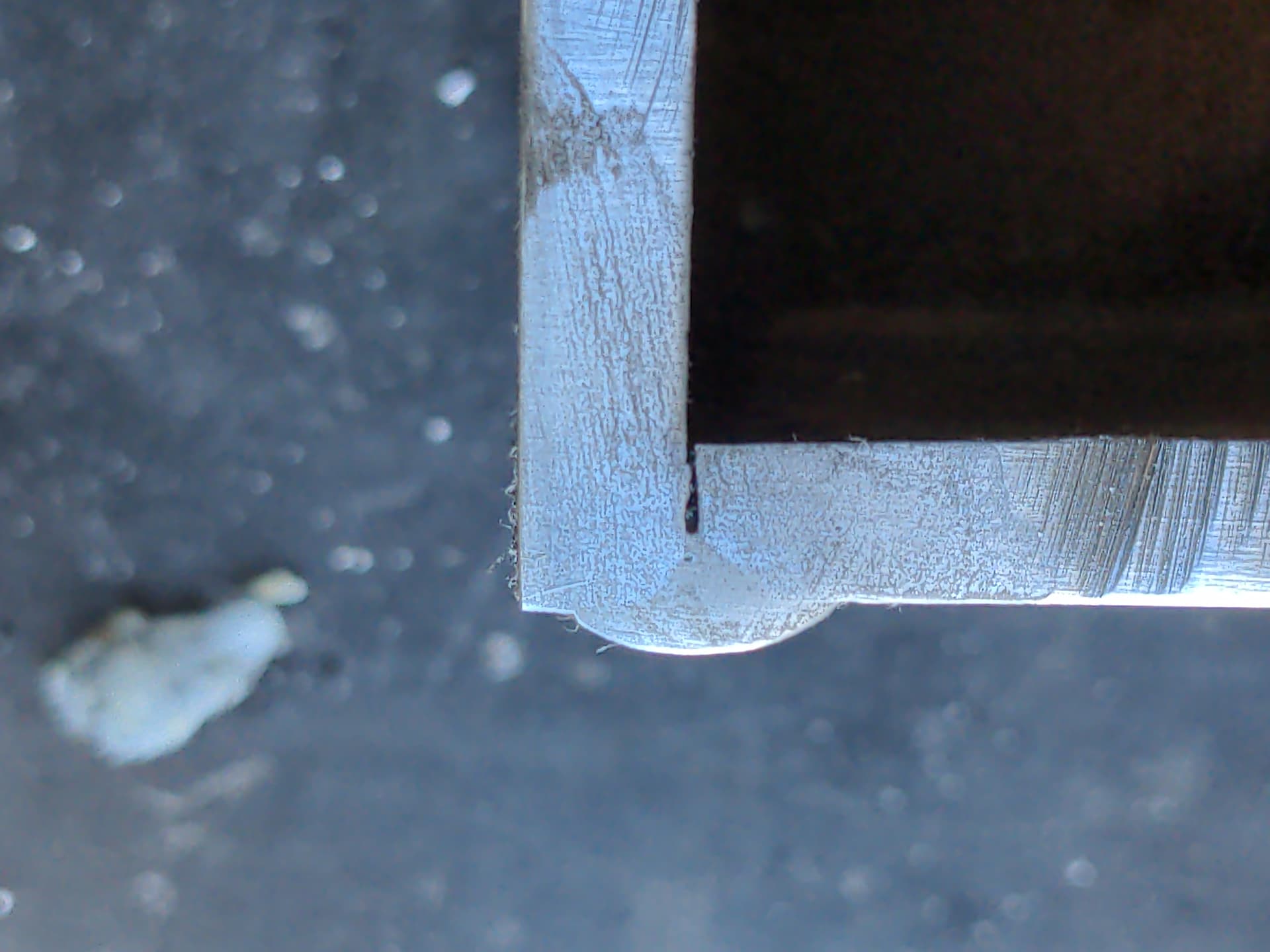
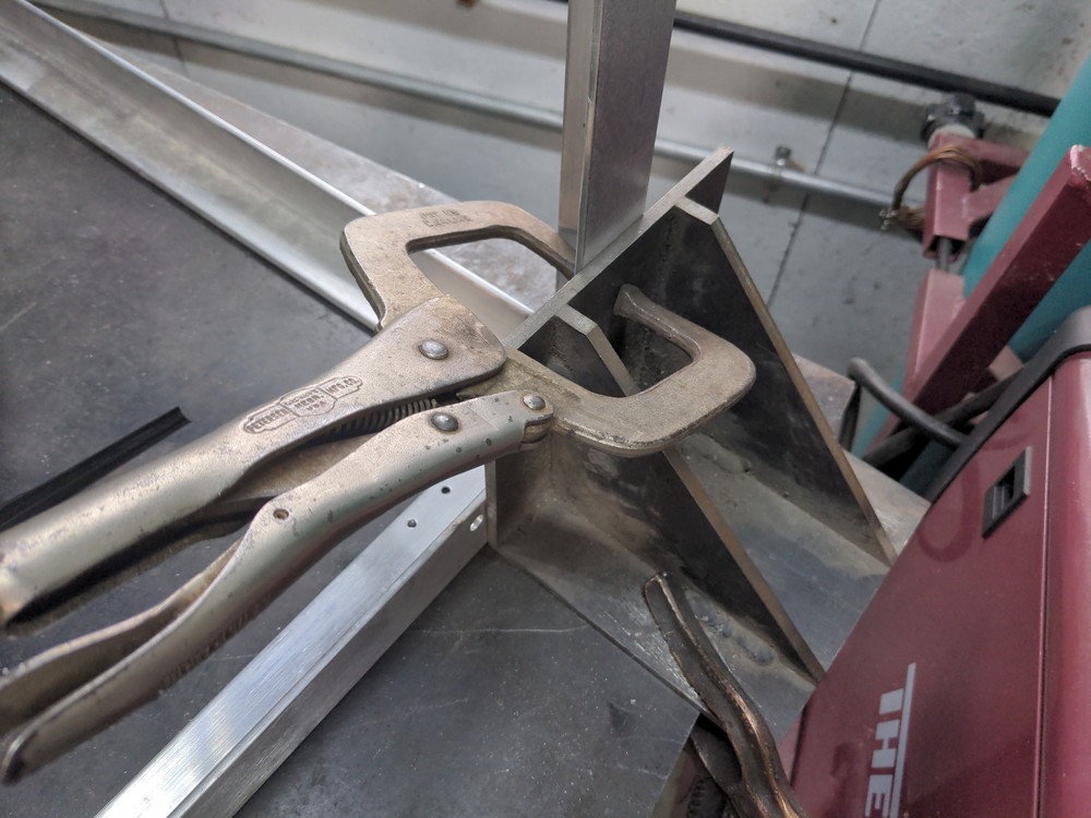
Forgot to get a pictures of machining the parts for pitch movement. 1" ID tube for the cross-piece, but I didn’t have any thick wall tubing with a small enough ID to tap 1"-8, so I machined that from solid and milled a fishmouth on the front end.

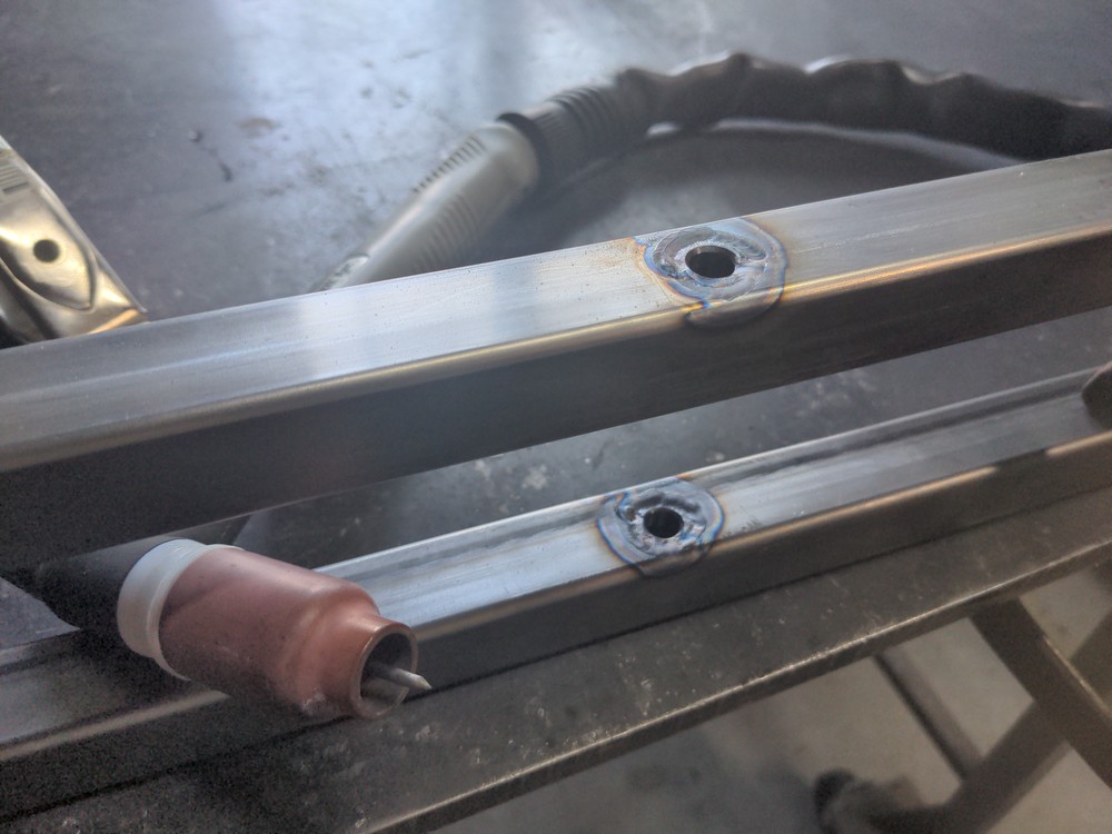
Fitup in a vise for tacking. I stuffed bits of sheet metal scrap in both sides to center it up.

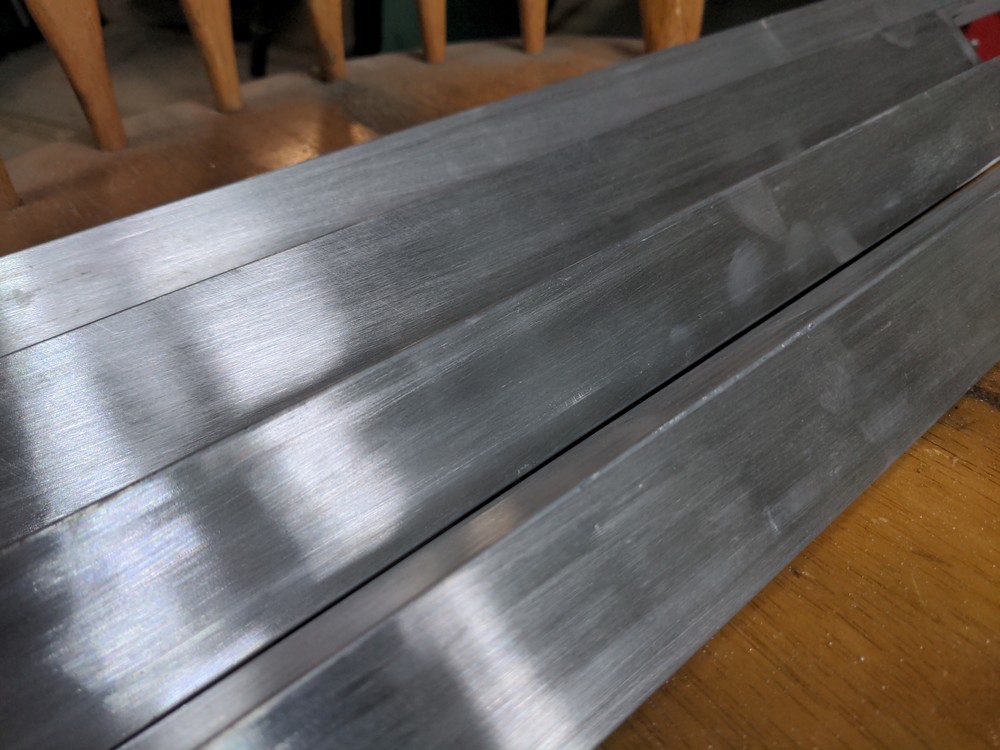
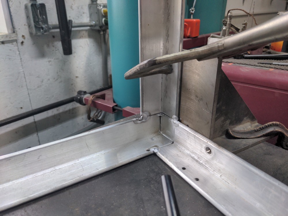
Then weld that at look at the pretty colors!

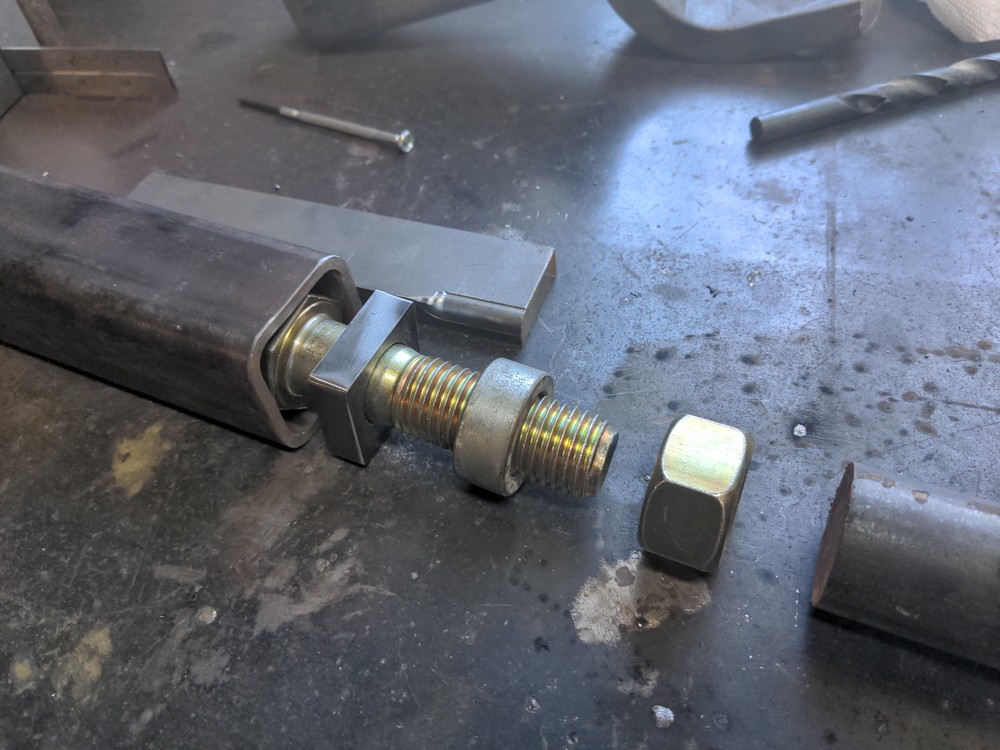
So this part threads onto the bolt from the rear coupler. That jam nut and lock washer are really just to keep things from feeling sloppy. In order for this thing to actually come unscrewed in transit, it would require flipping the trailer over. To the left. Multiple times.

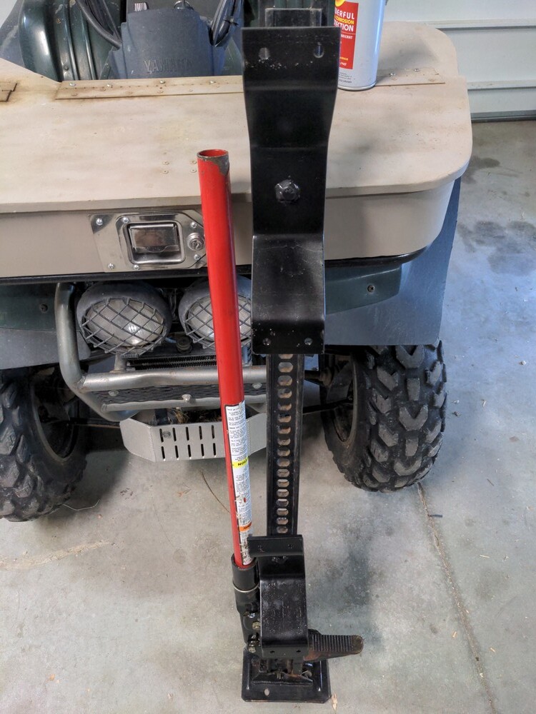
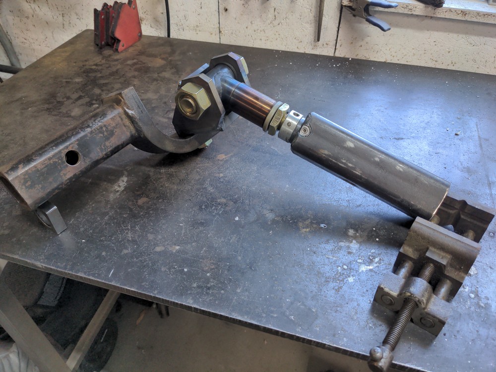
Overthought-out hitch complete!

An example of it’s movement range. This could pull trailers places I personally don’t really want to go!

Paint soon, test later. You’ll see this again when I get to go out and test it on the trail.

How is the yaw pivot joint lubricated? Or is it just a dry bolted together joint?

The 5/8 bolt runs through a hardened bushing that will get greased. The bottom of the clevis and top of the stinger are flat steel on steel. I’m trying to decide if I grease it a bit and try it, or maybe make a thin ~2.5" wide delrin spacer and see how it survives the pressure.

Macro etch testing

I’ve got some important welds coming up on some ~3/16 channel. I’m pretty confident in my flat butt and lap joints at current settings but this would be easier to do by welding vertical.

Different settings are required often depending on the weld position, and downhill welding reduces penetration further. I’m just going to leave my settings where they are though and lets see what happens.

First setup the test joint.

Hrm… well if the inside is anything to go by I should have probably doubled that gap width in the joint.

So then the weld gets cut in half, and polished up a bit with some sandpaper.

Ok yes, clearly very poor penetration there, but lets keep going.

Next you break out your gallon jug of phosphoric acid! Well alright, if you don’t keep any Alumiprep 33 around the local hardware stores do sell ‘Naval Jelly’ of which phosphoric acid is the main ingredient.

A cotton swab gets dipped and run over the still warm weld-bead. Here’s what shows up.

Hard to get the lighting just right for the camera. Zooming in helps. Even if the base metal and the filler rod are exactly the same alloy, the weld bead will show up since the grain structure between the two metals is different. The steel channel having more uniform grain distribution from the extrusion process, the weld bead having been a liquid is randomly oriented in the ‘as cast’ condition.

So obviously penetration only went about half way. The ~45degree angle it penetrated in at is a just ok depth-of-fusion. At the toe of the weld (that’s the left and right edges of the weld bead, right where that little hemisphere meets the base metal.) it’s pretty much just sitting on top of the steel channel.

So, options for improving penetration are:

  • Turn up the power on the welder (duh)
  • Increase the gap between parts
  • Bevel the joint so there’s a ‘V’ shape that increases lateral penetration
  • and when all else fails: suck it up and weld it out from both sides.

But I’m going to try and improve things mostly with techniques 2 and 3 and report back.

I’d sure like to make downhill welding work on this joint because it’s easy and looks nice and uphill welding on a non-fillet joint is like trying to push elmers glue uphill with a stick… and the glue is over 2000 degrees.

sigh I miss doing some welding. The hobbyist metal/welding shop closed up during the pandemic.

Just did a new search, apparently there’s a place down near Long Beach that has metal/welding/wood shops https://www.gearheadworkshops.com/ Hmm…must investigate.

Finally got the time to start the next fun project: an enclosure for the 3D printer.

Starting with cutting and coping the corners on the aluminum angle, and I decided to try another experiment with giving aluminum a ‘brushed’ look.


It’s an improvement. I tried this on some scraps with a belt sander and an 80grit belt and that was much too course. The finest grit zerconia belt they at at the hardware store was 120, and that’s what this is. Maybe not as nice yet as a proper SS wirewheel, but it’s nice to have an option to buff out the dings and scuffs from manufacturing when it matters.

So first the top and bottom frames:

Yeah, I can be content with those welds:

Next the verticals. I really thought this was a quick and clever way of squaring up one side of the angle, just checking the other with a square and tack around the edges.


It hardly worked at all :frowning:

I should have laid the front and back down on the table and clamped it that way. I ended up having to cut and fuss every single tack and angle back into square and straight and plum; lest I end up with a big 3D parallelogram and not a cabinet.

Partly this is recycled material too, so it’s not flawlessly straight in a few places.

So current status: it’s a box.

I’ve got rivets coming for the sheet metal siding and in the meantime I need to figure out how I’m going to make the doors.

Quick wiring issue that has me shaking my head.

I hadn’t paid attention to what that JDVcc jumper does on the various multi-relay boards for sale for Arduino type projects. It’s the one at the top center of that schematic, left of the green bar.

It’s supposed to be telling you how to run the coils off 5v when your signal is 3.3v, but this means if you just hook up a 5v Atmega with the jumper in place optoisolation has been completely bypassed?

and can somebody tell me where I should hook the ground up? It looks like that also crosses the optoisolator, is that ok? I’m running some lights and a 12v fan off these relays so I’m not likely to need the perfect isolation between raspi and relay coils but still…

Holiday week finally got me some time to make cabinet progress.

Much drilling and riveting of sheet metal, then I decided to paint the inside white for lighting and the outside black for fun. I had just about the right size scrap of 2024 aluminum for the back panel and used 24ga steel for the top and sides. Floor is just 3/4 plywood.

Kinda looking like a flight-case to me. I like how it’s turning out. I think I’ll get things wired up and put the printers in it so that’s out of the way before I get to work on the doors.

So there’s the growing pile of related enclosure parts. 2x Raspi’s running their respective printers, and one will also run Octofarm and the other running the enclosure control plugin. A 4 relay board can toggle the lighting and filtration fan, and some expansion room if I come up with other ideas. Also I got a DHT11 sensor to give me temp and humidity data. I’m going to experiment with just what 2 print-beds will do for heating a sheet metal enclosure in a ~40 degree shop over the winter. It might need some insulation, perhaps a blanket, or perhaps even something like a 20 watt cartridge heater to keep temps more stable for the ABS/ASA work.

So now it’s just mounting things up and playing with making the cable management look good. Time to print more cable-clips.

I just felt like I hadn’t spent much quality time with the milling machine lately, so today I decided to make some bus-bars for an upcoming electrical project.

Starting with some Delrin plastic bars, and 1/8x1" brass bar. It’s just under 12" long so I guess I’ll make 2 4" bars and a 3"

First task is to make a mess with the plastic parts. Mill the steps for mounting bolts and then cut them down a bit shorter too.

Layout was determined by playing with various sized ring terminals, and finding something that should work for whatever variety of wire/terminal sizes ends up in use.

Also I clamped the brass and plastic together so I could drill/tap everything at the same time.

Ended up with a combination of 1/4-20 and 10-32 screws on these. 2 of these are destined for use distributing power from a 20 amp 12Vdc supply. The other will just be in a drawer until I need it.

Clean off the marking fluid, bead blast for good measure:

Took me a little over 3 hours, including rummaging through boxes looking for the right parts to use. Hmm… now I’m thinking I should design and 3d print some snap-on covers to protect against shorts and bumps once installed.

1 Like

Those look nicer than the ones I made for my LiFePO4 battery cabinet;

I used 0.25"x1.5" copper bar stock clamped between some HDPE.

Well it’s winter again and I guess I can’t put off some upgrades to the gate opener any more…

The freezing fog and freezing rain is back, and it’s jamming up the actuators again. It’s usually a pretty rare occurrence but this is an unusually humid winter. This picture is from last week, and this morning I had to scrape even more ice off the actuators because of the mixed rain/snow we got last night.

The current monitors on the gate controller have mostly been doing their job. Detect a jam, stop the gate. Keeps it from breaking itself; most of the time. A plastic guide bushing on the end of one of the actuators broke at the screw head. So what to do about that…

Model it,


and print it!

Today I got around to building some actual covers to keep the snow and ice off the actuators. Layout starts on some old 1/16" aluminum sheets.

The almighty companion angle cube once again helpful in determine bend angles and spring-back.

First one’s bent up. Next is test fit.

Um… I’m really not sure where that extra 2 inches went. Clearly this should have been 16" wide not 14". Alright well, that’s alright, I can make it work.

Winglets! I test fit these again with the gate open and closed and it’s just fine now. It was pretty close to dark and starting to snow again so I’ll have to get these installed tomorrow but for now, biggest step done toward further gate-control upgrades.

I’ve been getting started on a new box tube and sheet metal sign project this week. That means an excuse to buy more tooling!

My Yard Store order arrived yesterday. A 5/32 pack of Cleco clamps, some fresh rotary files, a countersink micrometer depth-stop, and a tool I’ve wanted for years- a rivet fan.

It expands sort of like a pantograph and provides 20 evenly spaced, adjustable holes for center punching a line of rivet holes. Much faster than marking every 2" with a sharpie and a straight edge that’s for sure. I should have bought one 2 trailers and a printer cabinet ago.

Apparently they included a new toolbox sticker too :slight_smile:

But before the interesting sheet metal parts happen, I gotta get the framework done first.

So cut stack of tubing.

Start welding.

Drill some 5/8" holes for the 5/16" connecting bolts.

Then turn some bushings.

and here’s why the hole is so big. This attachment will make more sense when I get the other half of the frame done, but this piece is being bolted to another through the tubing. That leaves space for moisture to make its way in past the bolts, and build up in the tubing, and cause corrosion. Welding these bushings in means the whole thing is completely sealed.

So that’s 2x cross-frames done. Today I’ll keep going on the larger square frames these attach to, and figure out a jig for all the wall-brackets this design will need.

ahem…

THIS WAS A TRIUMPH

I’M MAKING A NOTE HERE

HUGE SUCCESS!

I have agonized over how to cut 4, 3’ radius sheet metal circles for a couple weeks now. Best thing I could think of, was model an idea after the wood-router circle cutting jigs. But a router bit isn’t going to do very well with 18ga mild steel, so I started designing something that would work with an air-grinder and a carbide burr (aka rotary file).

Why 4 half circles? Well try as I might, I couldn’t find anyone selling sheet metal over 4’ wide, and I need to make 6’ circles.

CAD and 3D printing made making such a jig really fast and easy. Took about 18 hours for each major part to print.

at least they look cool, IMO. We’ll see if they survive the stresses put on them.

With the paddle taken off the die grinder it slips in the largest hole and gets squeezed in place with a 1/4" bolt. Then 2 pieces of EMT electrical conduit goes in the other two.

Feels pretty stiff, although the plastic is a bit slippery and didn’t grab the tubing as strongly as I would have liked. I kept a close eye on it in case vibration would start to make things slip apart.


So before I can test that out, time to wrestle the first of 4, 4’x10’ sheets onto the table. That was about as much fun as trying to punch an octopus I’d imagine…

My trammel isn’t 3’ long so I stuck a nail through the sheet and tied a marker to a piece of paracord.

Rough cut just a bit outside the marked lines with the electric shear. I cut this first piece 2" too big so I could test the grinder idea before cutting the final size.

So after the test cut, comes the first final cut. This tool doesn’t move fast, but it’s working!

I’m stoked! My arms hurt now but I’m stoked, that went great! Now I just have to do that 3 more times.

Pretty much took me all day, but it’s done. I don’t know when or if I’ll use this grinding tool again, but it’s getting it’s own spot to hang on the wall even if just as design art.

Also after 5 cuts through this material, that new carbide burr is smoked.

So that took a while, and boy did it make a mess. Sawdust and metal chips sprayed all over the place. Right now, I do not care. The hard part is done, time to wash the oil soaked dusts off of me now. Shop will get cleaned tomorrow.

These are going to be horrendously intimidating to mount… after cutting into that area.

I really enjoy the use of 3D printing for a “I have a problem; I have a 3D printer and know how to use CAD; problem solved!” in this case. Printing out custom parts for weird one-off stuff seems an amazing use of a printer.

Very cool! I’ve done a few jigs on my 3D printer myself, although I’m getting better so I have to do fewer re-prints, still usually need to make a few copies.

Next time maybe get a roll of basic rubber and use that to slip between the plastic and the tube and clamp onto that? Rubber should help hold into place wonderfully on both materials I’d think.

Much less effort to make the straight parts than the circular ones.

Now it’s time to drill and drill and drill. @Syonyk got through the bulk of it while I was making brackets. The circles can be mounted to the frames and then comes the crosses.

Why oh why didn’t I buy myself a rivet fan years ago? They’re great!

Scale looks really good. Some adjustments are being made to the stand-off distance between the cross and the circle but I’m getting close to being able to test fit lights.

More layout and some trimming of sheet metal. Then drill for screws and start mounting the LED ropelight.

That powers up and the splices and everything work ok. This cut-able rope light is pretty nice and easy to work with so far. I like it.

Time to set it up for proper field testing. Now we wait…

SO BRIGHT… SO BEAUTIFUL…

Actually it’s not that bright, the camera definitely makes the area looks more lit up than it is. That’s just fine though, I think the lighting is just right to make the signs clearly distinct and visible from a distance without being an obnoxious spot-light shining down the street.

I’m stoked! It’s everything I’d planned on it being! It’s going to the powder coater next week!