Hi I’m new here.
My friend Daniel showed me this page and I wanted to share a recent project I made.
I drive a 2014 Prius which has a navigation display and reverse camera like every car does now.
I saw a Honda Civic with a camera on the sideview mirror and thought “I should do that” so I did.
I added some generic reverse cameras to the undersides of my side view mirrors and routed the wires inside the car.
Then I figured out the circuit I needed to design.
I found the schematic for my car and the head unit has a reverse trigger input as well as four wires for power and video signal from the reverse camera.
I figured I could cut the video signal lines, take the incoming reverse picture, send it to a switch, and have the output of the switch route to where the reverse video was originally going into the head unit.
The switch’s other inputs would be from the side cameras as well as an option for front camera in the future (for fun).
I have experience with pcb design and arduino programming so naturally I figured I could make this happen with an atmega328pau, a mux/demux ic for switching, and some photocouplers to handle the signal triggers.
For the triggering system I cut the reverse trigger signal to the head unit and threw a diode in series with current flow. I found that the head unit looks for this connection on start up.
On the anode of the diode I tapped in a wire to use as a reverse signal trigger so the micro knows when to switch to the reverse camera video.
On the cathode of the diode I tapped a wire to use to trigger the video screen whenever I want.
I also tapped into the left and right turn signal outputs to use as triggers for the side cameras.
All of the trigger inputs are 12V (14V actual because its a car battery) and go to the LED side of the optocoupler. Since I have three triggers (reverse, left, right) I picked a four channel optocoupler (TLP291-4) and put the triggers into the led side of the couple. The photo transistors on the other side have their collectors tied to 5v and their emitters pulled low with resistors and are also connected to inputs on the micro.
The fourth channel I used as the screen trigger output by using an output on the micro to turn the photocoupler led on. The phototransistor’s collector is connected to 12V and the emitter to the cathode side of that reverse trigger diode I mentioned earlier.
The video signal inputs go to different input/outputs on the mux with the common in/out going to the main video output line which goes to the head unit.
The board has a switching buck regulator to take the battery voltage down to 5V for the logic. This was just a generic buck pcb I got on ebay.
I used RCA style connectors for the video lines.
I found some terminal connectors that have little levers you push to install bare wires for all the trigger connections.
I also added connections for physical dash switches to turn on the reverse or front camera at anytime.
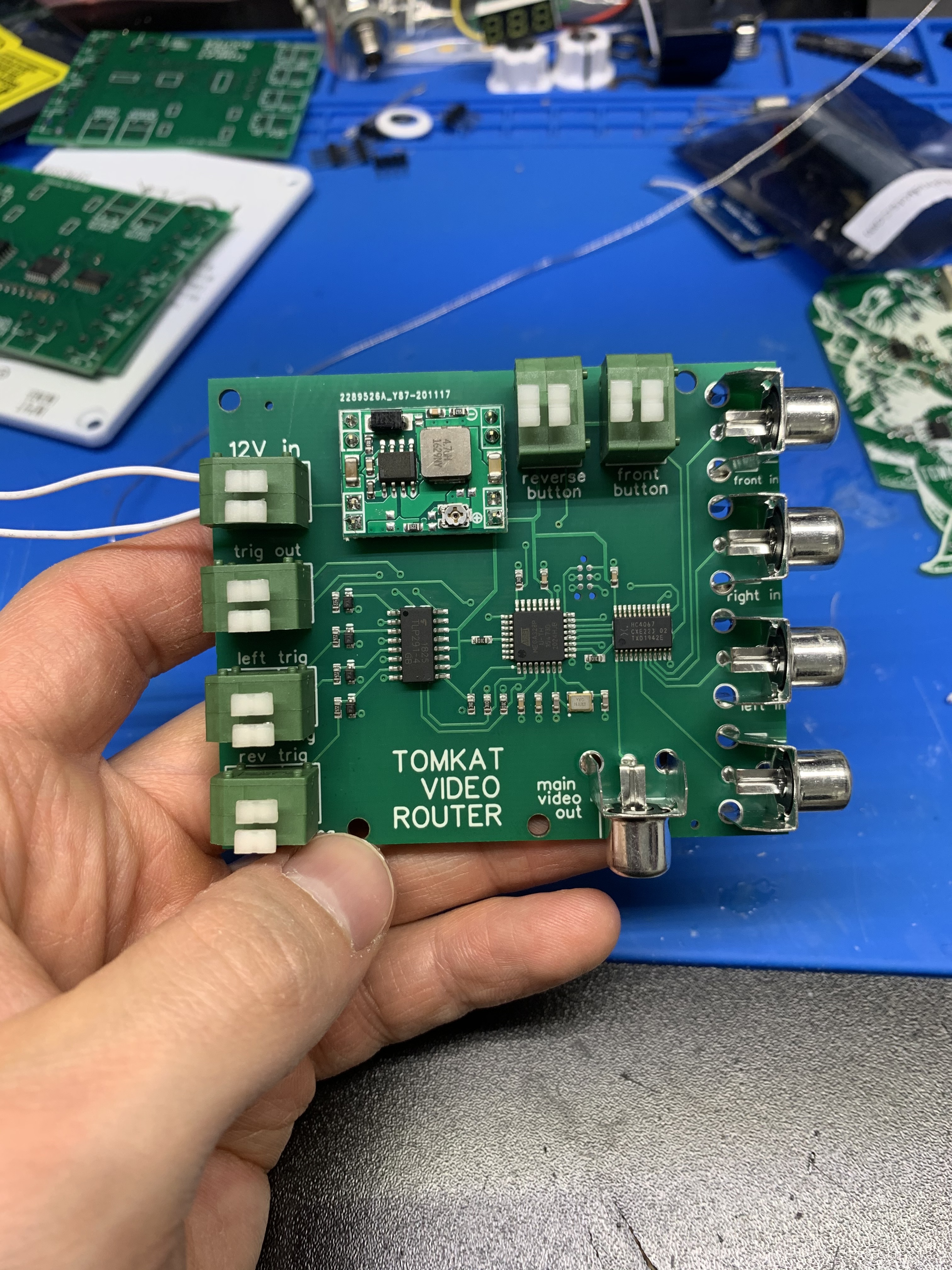
Heres the completed and populated board.
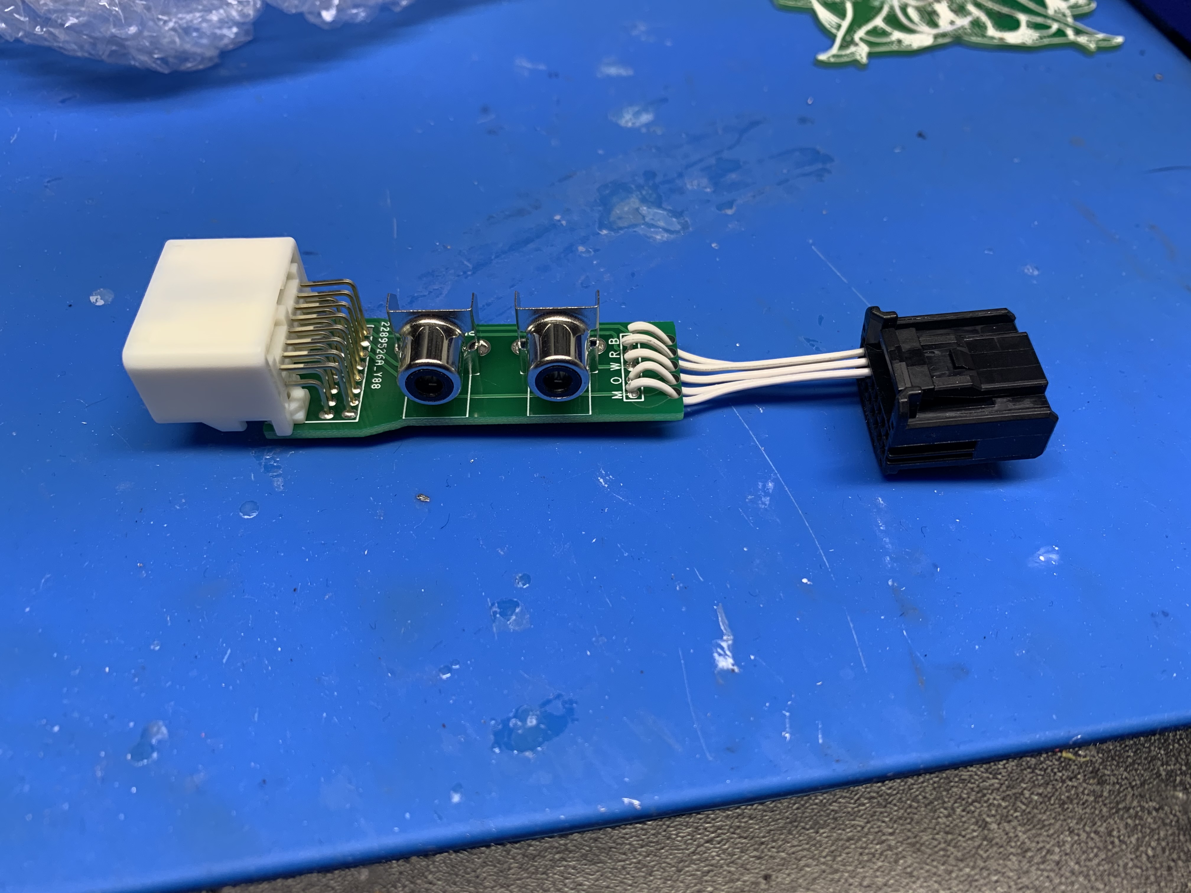
I didn’t want to chop up the wires behind the head unit and solder back there so I found the head unit connectors from mouser and designed a little adapter pcb to cut into the video lines and use RCA jacks to tap in to them.
The code is very simple.
If there’s an incoming trigger - switch to that trigger’s camera signal - enable the screen display trigger - keep the screen trigger high for 3 seconds and then release everything.
if the dedicated reverse camera button or front camera button is pressed - switch to that camera - enable the screen trigger - hold high until the button is unlatched.
So I wired everything up and…
It didn’t work. Of course not, why would a project just work perfect the first time?
All I could make happen was if I took out my adapter pcb and plugged in the reverse camera harness directly, if I hit any trigger it would show the rear camera for 3 seconds. This was basically the correct function but if I had my adapter in there which would show the switched video signal it wouldn’t work.
SO after lots of testing and and guessing I found that when you initially start the car the head unit checks to make sure there is a video signal coming from the reverse camera to confirm that the car has this feature.
The fix
All I had to do is add a line of code that-
at initial power up - switch to reverse camera feed for 5 seconds and release
this way the head unit sees an available signal to display.
Now it works as it should. The feed from the side cameras is kind of fuzzy, might be because I had to splice some of the wiring which messed up the shielding. I Initially thought it was from switching video signals with a demiltiplexer but I tested it with the cameras outside of the car on a monitor and it worked just fine, nice and clear. Plus the reverse camera feed is perfectly fine.
Here’s a video of it working:

Let me know what you guys think and yes I know I could just turn my head to look in my blind spot but whats the fun in that?


