So I’m about to embark on this project! Well, in the next few weeks.
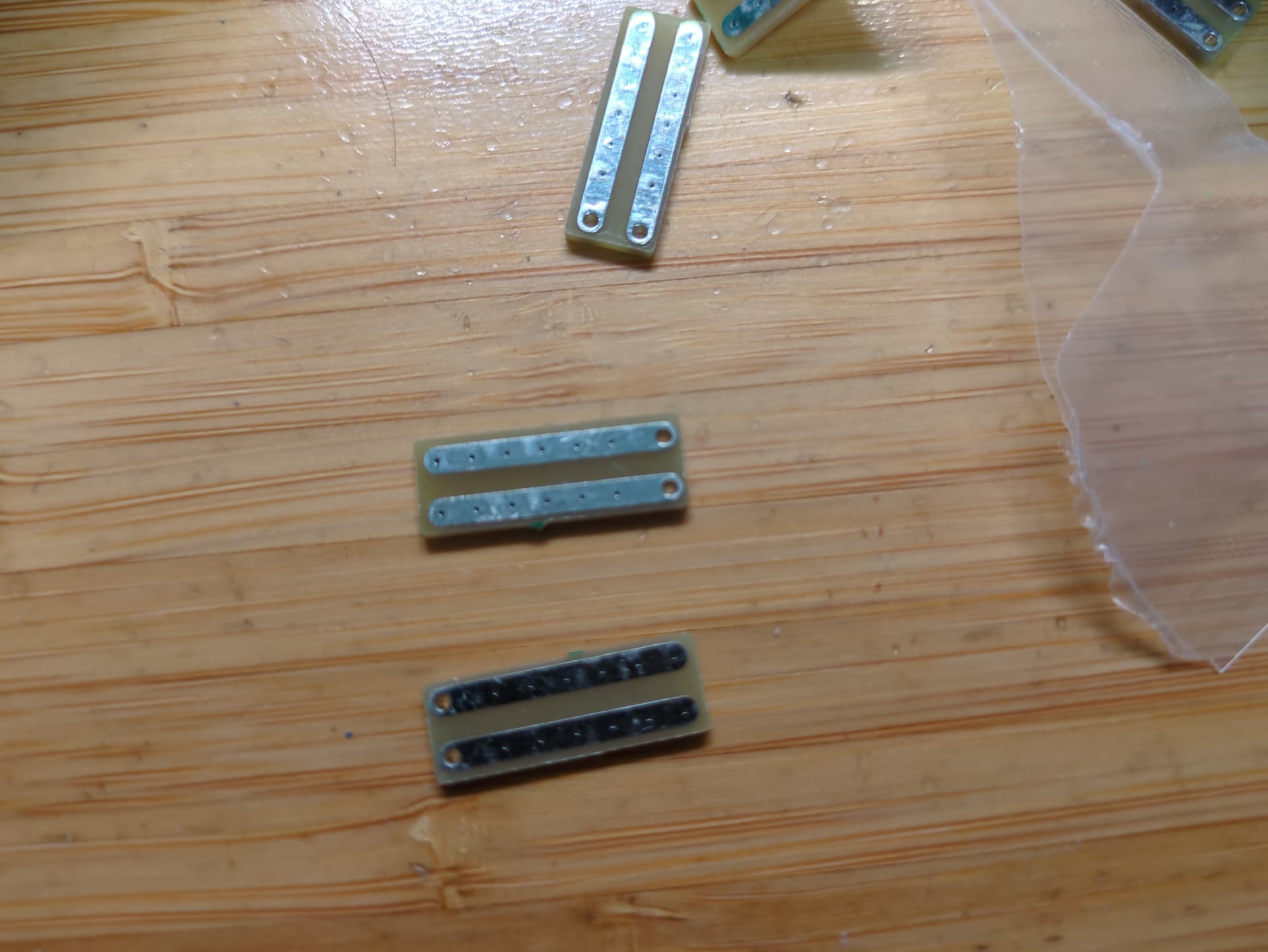
@CoolModine I got this one, with this pen since I decided having it side-by-side like this, with pressing down for contact, would make it a bit easier to be consistent and also avoid the possibility of having the 2 pen tips too close together.
Also @CoolModine, these are WS2812, so 5v per pixel, individually addressable, so can’t have the LEDs in series to make up the “~30v” if I did 8s1p. Not the way these work, unfortunately.
Going to get all the cells down to ~2.95-3v each (spec sheet) says 2.5v min, so well discharged but not close enough to be close to damaging them.
And based on my current physical space estimates, I can do a full 8 cells, so I’ll be doing 4s2p. No bucks small enough that’ll do for 36v (well, 33.6v full charge) → 5v that’ll fit. So 16.8v on one that maxes out at 24v seems about right. And has a nice fixed 5v solder output, and even better an Enable pin. So I can hook it up to the ESP32 and WLED has the concept of a relay pin when turning on/off. So I can potentially have it “on”, but just the micro is on, and the strips won’t even draw quiescent current.
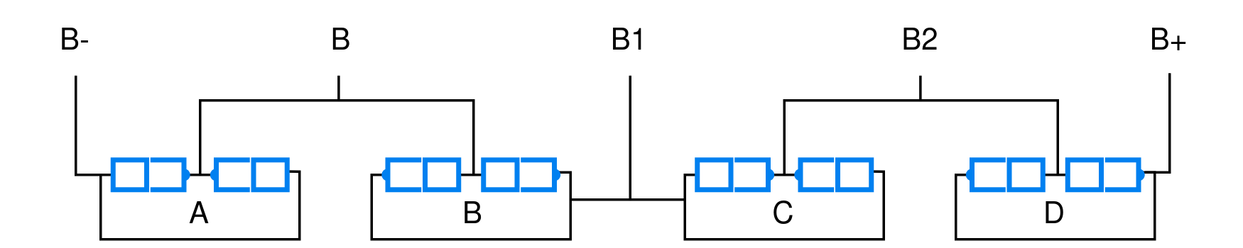
So going to have to do the cell groups end-to-end with each other, I’m thinking this order, and those are the BMS solder points. 0.15x6mm pure nickel strip, at absolute peak, which I should never reach with any reasonable config is ~5.5-6a from the battery, so those strips should be plenty. In practice, probably 2-3a, maybe even less.
So I think this arrangement, although with B-C + to - connection, that’ll be a lot shorter, but I think it’ll be OK as I’m not going to really be close to limits, so the marginal resistance difference should be OK. I’ll just have to use lots of kapton tape to wrap the batteries with the nickel strips, and will end up with multiple wraps, and then once I do the balance wires & 18 awg from one end to the other, do a long heatshrink on the entire thing.
And as I said, 18awg solid copper to go from one end to the other to get the power to the other end of the battery stick, and probably 24awg for the balance wires should be fine with minimal bulk.
Also contemplating adding Adafruit INA260 High or Low Side Voltage, Current, Power Sensor : ID 4226 : Adafruit Industries, Unique & fun DIY electronics and kits into the battery circuit (after the fuse) to add monitoring to the micro. On the other hand, I can probably do this OK by planning to measure current usage before soldering on the on/off switch, and put my multi-meter in the middle. However, it won’t give me voltage readings (aka battery %), unless I do some kind of crazy voltage divider or something and pass it to a GPIO. There is WLED/usermods/Battery at main · wled/WLED · GitHub, but that is talking about a 1s reading the voltage, rather than 4s. That’s really more what I’m after, a current battery %. I do see using op-amp, but that’s more reading each cell individually, not a single value of the pack as a whole. Any thoughts?
Separately, for charging the battery, I almost want to see if I can fit in a buck-boost CC/CV to charge from a USB-PD source, specifically a 12-20v USB-PD source. The problem is if it’s 12v, most chargers will only do up to 3a (regardless of cable), so I’d need to limit my charging to 2a@16.8v, ~33W, which would barely fit in the 36W of the USB-PD. 20v@3a is no problem. I’d really prefer to charge at 3a, which will give me ~50W. Given the entire pack is juuuuust under 100Wh (aka OK to take on a plane! hahaha), that’d probably be about 2.5-3 hours from drained (~3v per cell). Which more or less matches the battery spec list at 0.5C, although doing 3a@16.8v pack voltage would give me slightly below 0.5C charge per cell. If I can find a small enough buck-boost CC/CV, I suppose I can experiment (outside) of the cane with a load tester and check if it’ll work OK at 12v@3a USB-PD, or if it’ll just try and over-amp and cause the USB-PD source to shut down.
I did also just find https://fpx.oxplot.com/, which seems really cool. Seems like I can program it to do 20v@3a primary, and otherwise negotiate at 12v@3a.
EDIT: I also just realized, I can use a smaller switch that doesn’t handle the full current load. I simply wire it to handle the ESP32 3.3v load (100-200mA max? Less?), which then can trigger a MOSFET or Relay which can handle the full load. And then I also don’t have to worry about wiring in the Enable pin on the bucks for the LEDs. Makes more room for the charging plug, and also let’s me add in a well integrated, sturdier metal “handle” that I can use to more easily pull the whole thing out, as needed. I have some of this small dual boards. Shouldn’t be fine for both load and heat, since I won’t be doing any kind of fast switching/pwm, and the possible battery load is well below max. Or I can just use a standard 3v coil 28v DC 10a relay. That might be easier, and also is a physical disconnect, rather than just powering off. Should still be safe through a MOSFET, but still.