The State Of FDM 3D Printing, according to me

Well I bought a thing. My endless quest to learn how all things are made everywhere continues. After a winter of reading about all the different levels of ‘additive manufacturing’ I decided I just had to see what all the fuss was about. FDM plastic printing started to look a lot more versatile than I would have figured. Actual functional, structural parts that can survive (more or less) about as well as any injection molded part. At least that’s how I understand it, but I was intrigued enough to see for myself, and start some discussion about the results here.

Enter the Ender 3


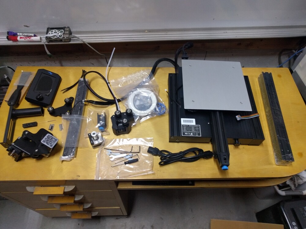
Now I find myself with an Ender 3 v2. Most of what I consider best in life is ‘some assembly required’, and this is no different. I’m a machinist. I’ve trammed milling vises into square within +/- 0.001"-per-4" travel using hardly more than a piece of cigarette paper. Assembly and tuning of a 3d printer will not best me.

Initial setup went just fine. Google-translate written directions were a bit hard to follow in places but copious online posts and videos about these machines will get you through all the tricky parts. Not to belabor the specs of this specific machine too long, but I also added about $20 in upgrade parts that internet reviews considered pretty much essential to be installed with the machine first thing. A metal drive mechanism, flat wound bed springs, and a higher temp Bowden tube should head off several problems.

First prints

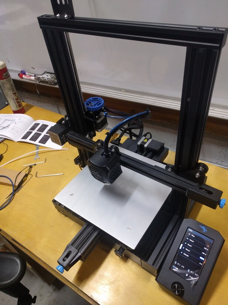
So with initial setup complete, bed levelled, and Ultimaker Cura installed as the slicer program, lets see what the total defaults look like:

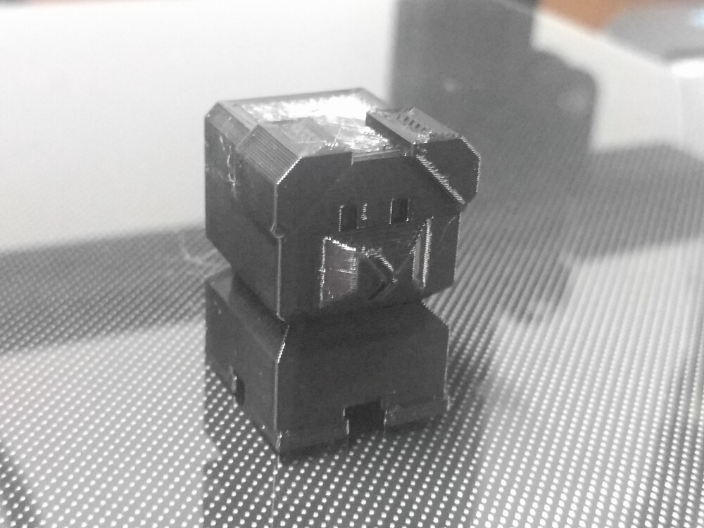
I’m… not often left so pleasantly surprised. Total defaults, stock settings, first attempt and printing anything and this is the result? This is awesome!

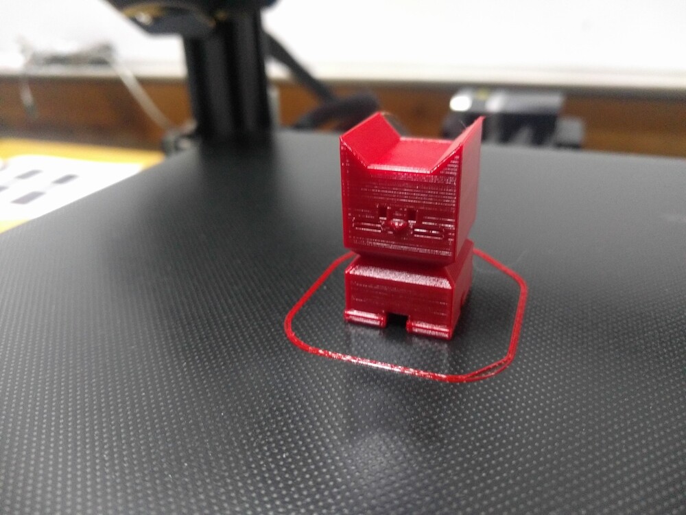
Shown above is a ‘Calicat’, short for calibration-cat. It has a head that’s 20mm x 20mm, a tail that’s 5mm x 5mm, and all angles are 45 degrees. It’s #1 job is to test printer calibration, verifying that all it’s features on each axis do indeed turn out to be the dimensions listed. Since that seems to be just fine out of the box, I’m now printing a growing army of the little guys. It’s a terrific item for testing materials and settings. Different speeds, different temperatures, all the hundreds of changeable settings in a slicer program can be experimented with and tested to see how it might change surface finish, accuracy, layer strength, etc.

So I’ve since bumped up temperatures, and I’ve bumped up feed rates, and I’ve been printing stuff pretty constantly just trying to get an intuitive feel for the interactions of such settings, and a general idea of the strength of parts at their various settings.

So what does a machinist want with a toy printer?

Well I think the short answer is it’s not a toy. It can print toys if you want, but this is definitely a tool. A tool that can print more capable, structural, functional components than I realized even before I bought the thing. Sure, it can’t do everything. I’m perhaps rather more used to that than most people; for every manufacturing technology and tool has it’s strengths and limitations. The key to good design is to be keenly aware of all these, and design parts that do what you need around the limitations of the tools you have available.

Much as I love all things made of metal, I can’t deny that plastic is sometimes the superior material. For weight, impact resistance, or electrical/thermal isolation plastic has it’s place. I look forward to exploring ideas and expanding my CAD skills at the same time.

As it stands I’ve got 3 major interests in making things with this printer:

  • Electronics enclosures: Totally custom enclosures and housings for my totally custom PCB electronics projects. How could I resist that?
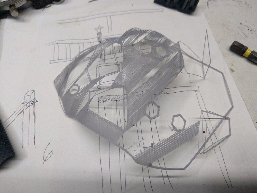
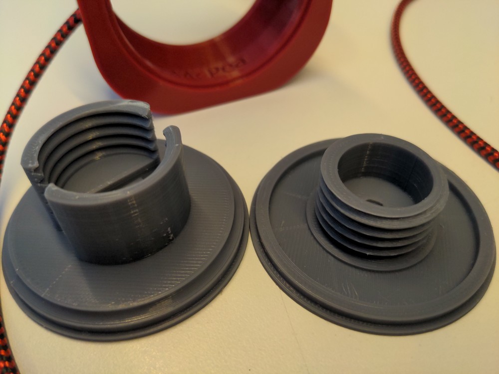
  • Compliant mechanisms: Given the flexible nature of plastic, there’s some designs floating around of parts that perform some kind of spring or cam-like function without any external parts. The printed object is the spring. I find this capability quite interesting.
  • Hybrid designs: Having access to more metalwork tooling that most I’ve got a growing list of ideas for hybrid mechanisms. The kinds of parts and projects that might just be impossible or too difficult to machine purely out of metal, but might be made good enough (or perhaps better) with the right design of say, a 3D printed frame or shell; to be reinforced or supported by much easier to machine metal parts. Parts that provide bearing surfaces, stiffness, joint reinforcements and so on.

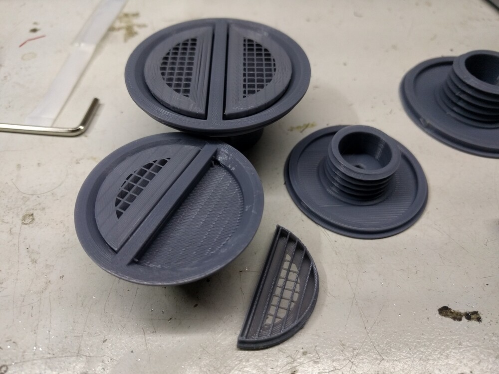
Back to more testing with red PLA+ material

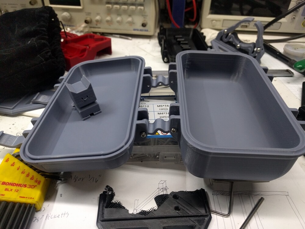
Besides tuning the machine, I’m learning a lot about design printing already designed parts. Snap enclosures, friction fit lids. I can measure and copy such design features and apply them to my custom creations with ease. Should be a lot less trial-and-error design changes needed with that.

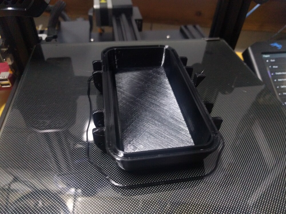
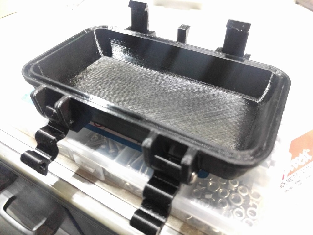
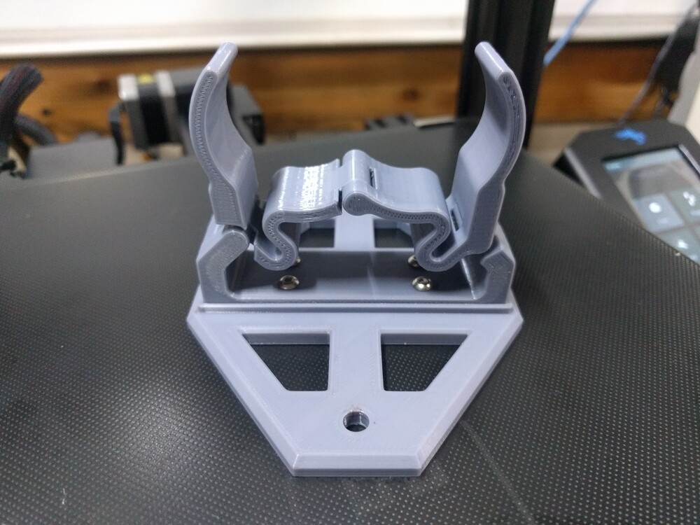
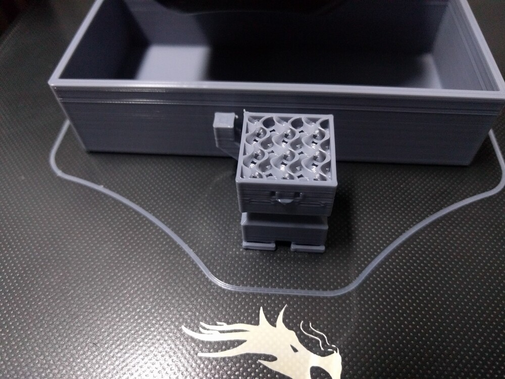
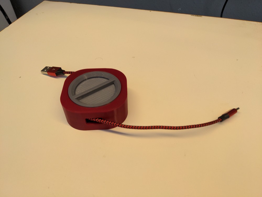
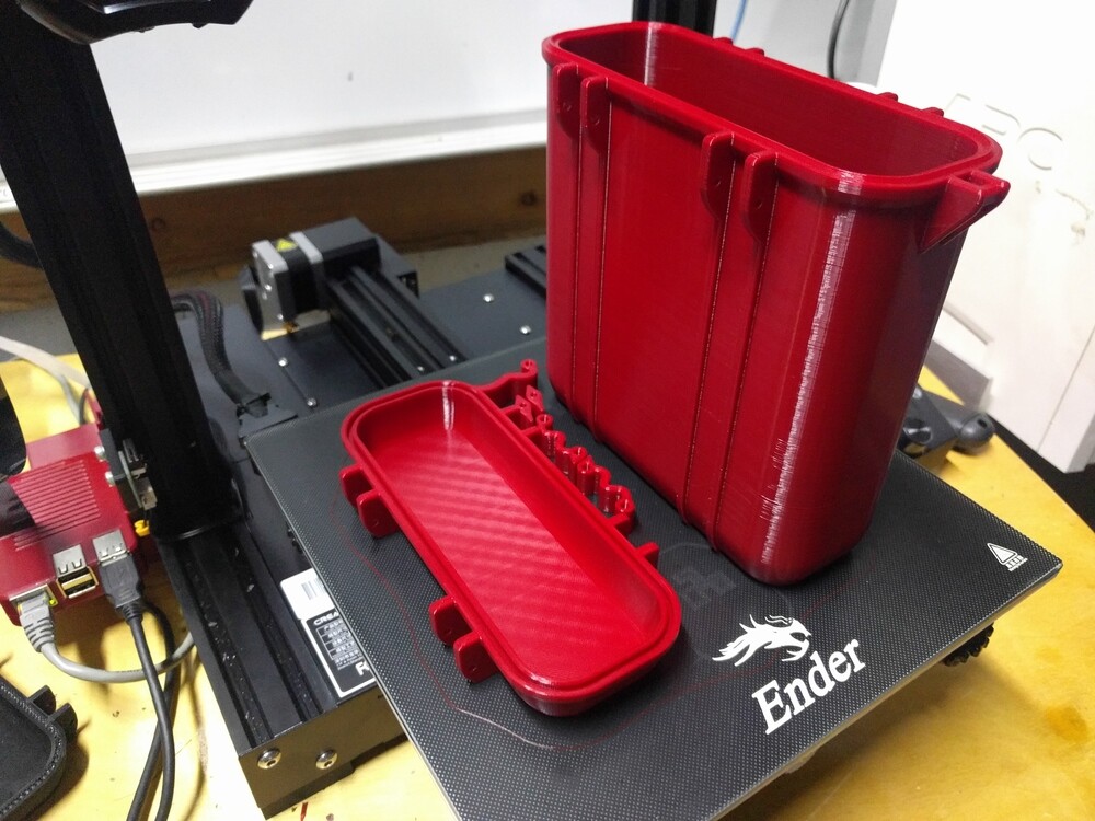
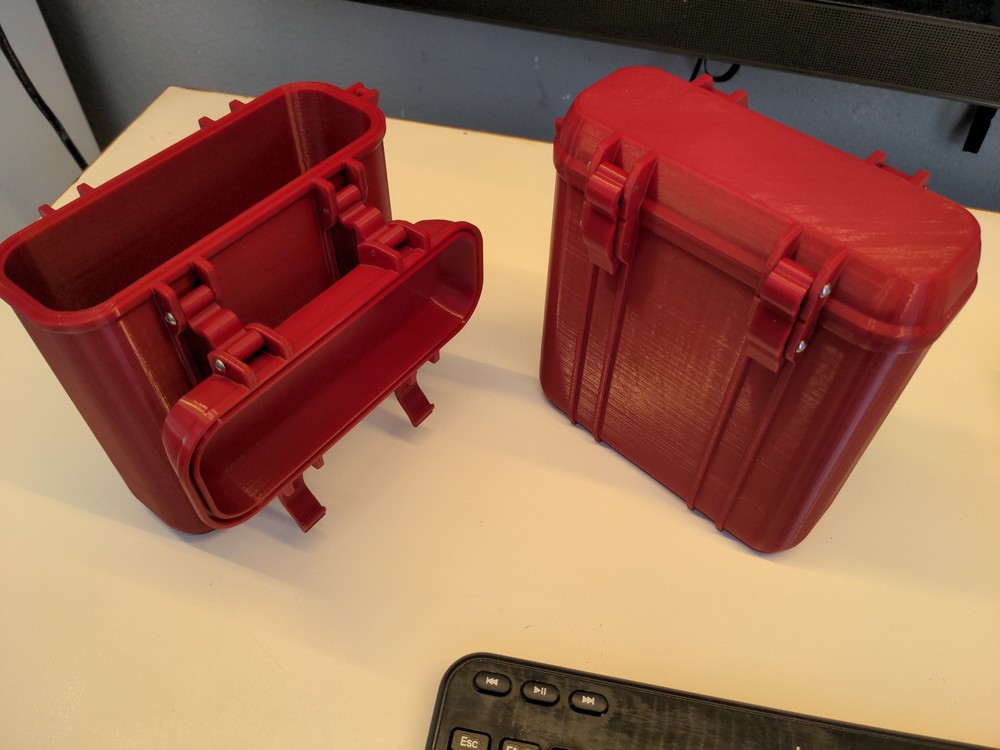
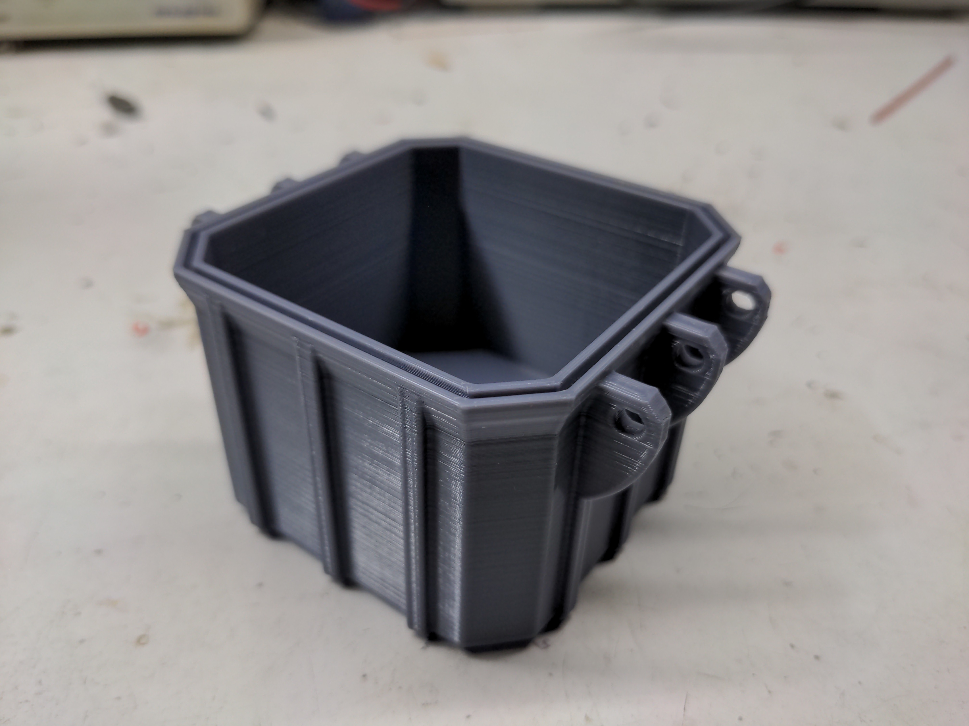
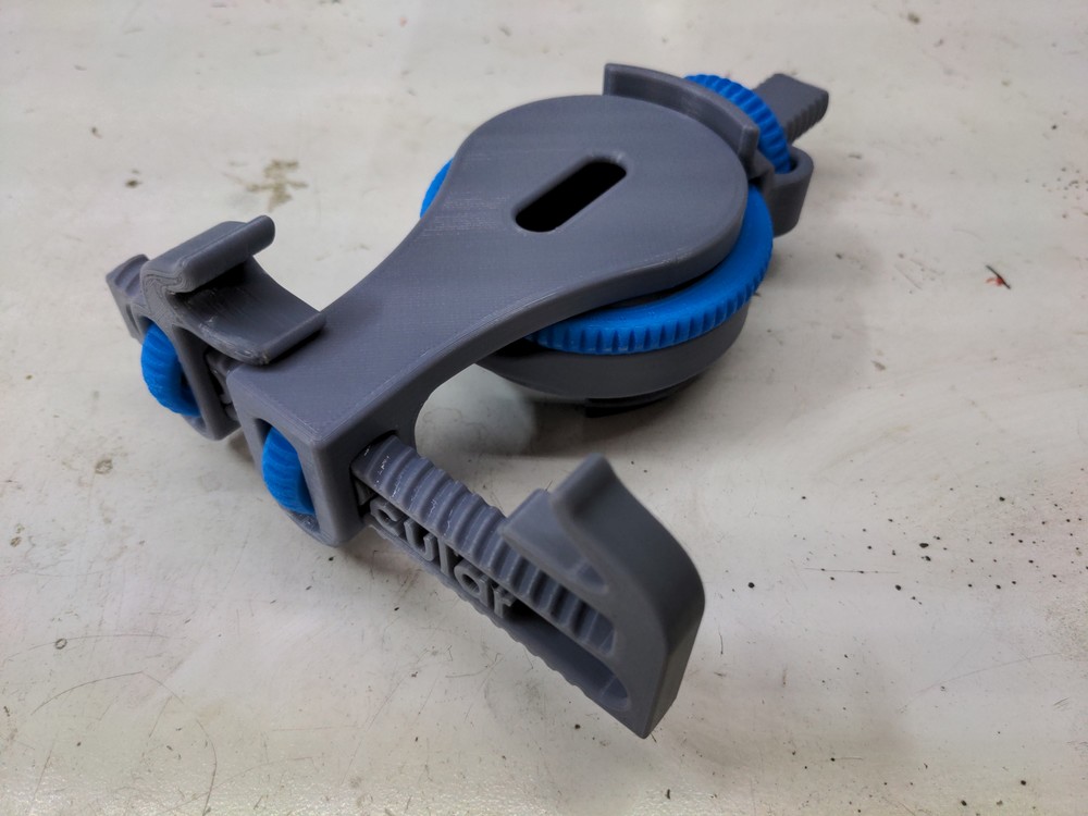
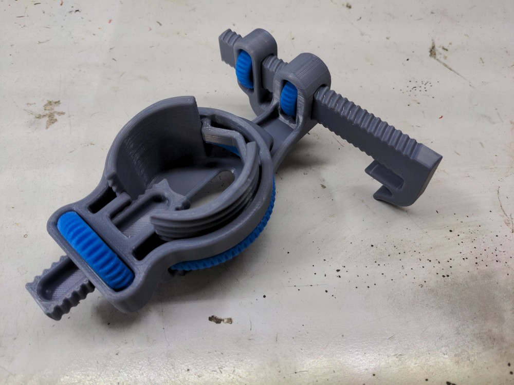
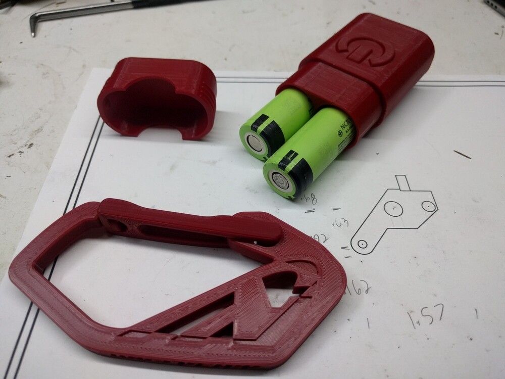
Here is the first compliant mechanism, a carabiner, and just a storage case for 18650 cells. The gate isn’t super snappy, but it is it’s own spring to close it. Sure, it’s not a rock climbing carabiner- a molded polycarbonate carabiner wouldn’t be either. I’d say it would very adequately handle at least 10 pounds on it, probably more.

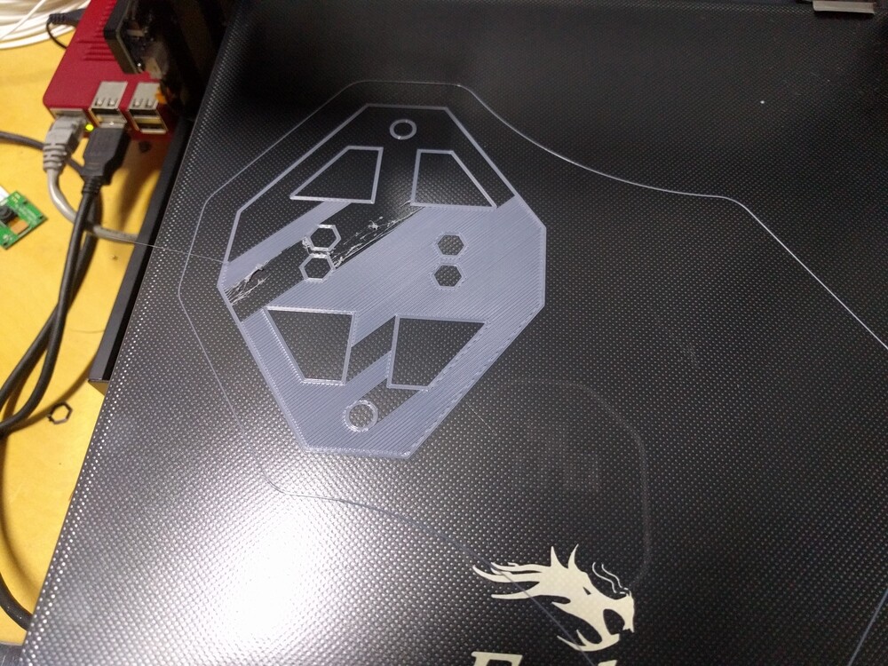
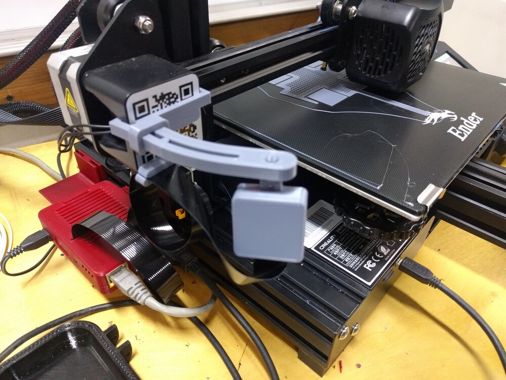
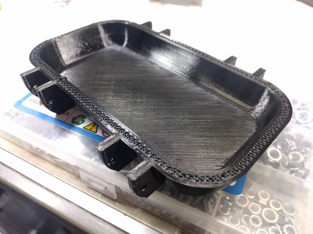
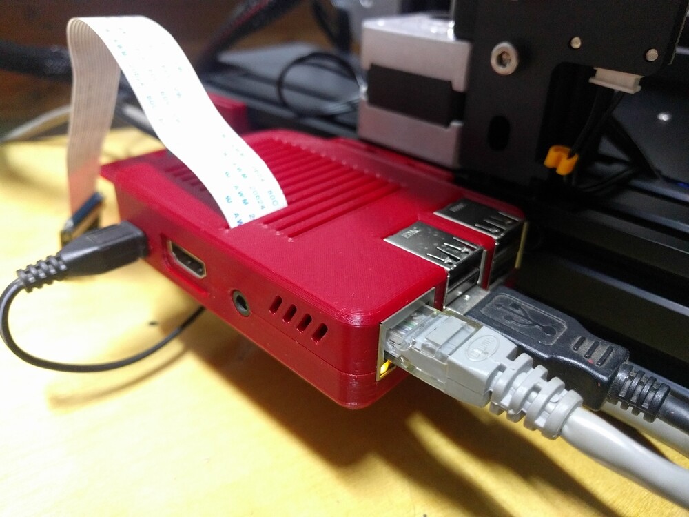
Next we have a Raspberry Pi case. This one felt great. Snaps together in two halves, wouldn’t know that feeling from a molded case. This one is now hanging off the side of the printer, running OctoPi for remote management and monitoring [more on that later]. Bracket for the camera will be made soon.

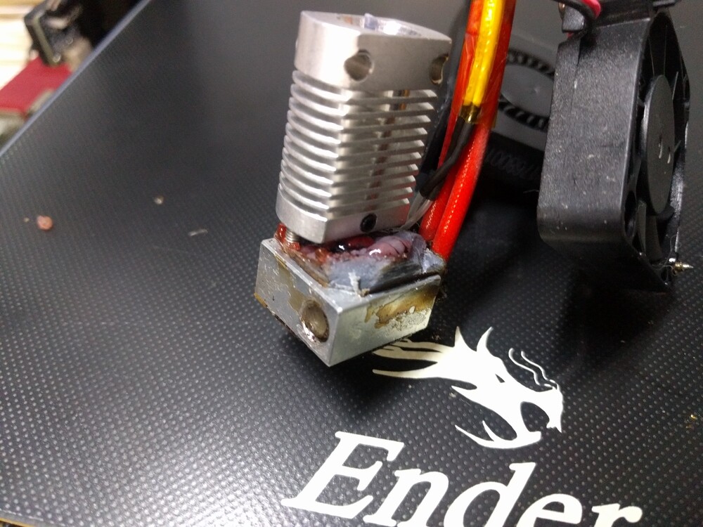
Man, PLA+ is proving pretty easy out of the box. I’m excited to try some PETG already (higher temperature resistance, better flexibility without permanent deformation). How hard could this be?

Oh…

Well alright, I’ll have some more impressive parts to show off after I solve some adhesion issues. Not doing very big parts yet. Going to get more confident things are working good before I turn the thing loose with 12+ hour long print jobs.

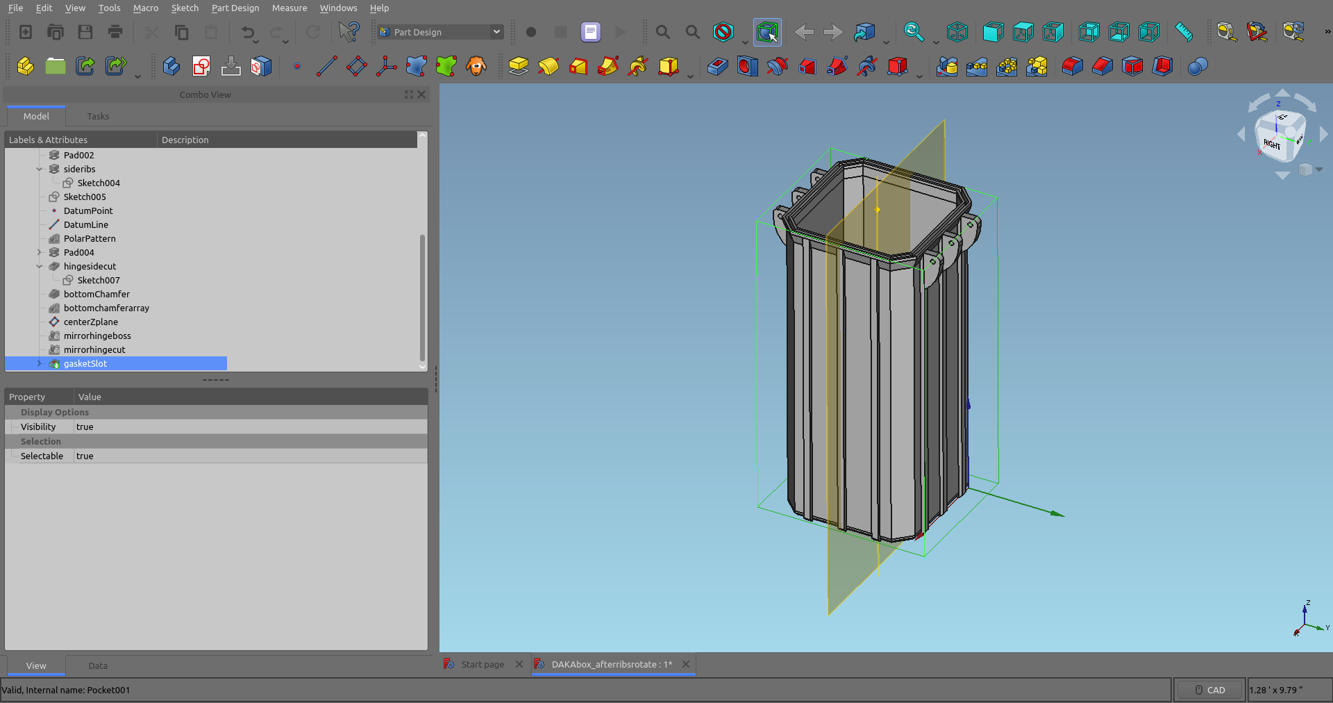
It’s still early days yet. I’ve got some parts CAD-ed to start my custom projects, and I will be documenting the results here. I’ve already got a few more parts done and settings to test and will post them up soon. In the meantime I’d love to hear ideas or questions; I’ll share what I know.

1 Like

I have seen these things. They are, in fact, as good as they look in photos, if not somewhat better.

And the calicats, after validation, are very well loved by a pair of small children! :slight_smile:

3 Likes

Recheck your levelling - that’s the biggest problem with the Ender 3… I have a pretty similar Cr-6 which solves a lot of the adhesion issues.

You could also maybe install a bl-touch for that self level.

Releveling helped, a bit more squish, and after looking at the first layer after aborting a print job for other reasons, I realized the lowest layer wasn’t fusing to itself very well from side to side. Looked like under extrusion to me.

So I set the first layer 5 degrees higher, and the first layer flow rate up 5%. Now the lower layers are sticking well and coming out smooth and shiny on the glass buildplate.

2nd update almost ready, just waiting on some latch pieces to come off the printer in a few minutes.

PETG experiments

Well I thought I was getting the hang of PETG. Couple larger parts felt like they stuck well for a while, now I’m back to really inconsistant results. Layer adhesion on the parts that stuck turned out terrific, feels very strong. Now I’m just working my way up and down the settings trying different temperatures, z-offset, flow rates trying to find something consistant. I might go back to the PLA+ I’ve been having such an easy time with and get back to this, but here are some working results so far.

Finally, here’s a Calidog that actually completed without breaking loose from the buildplate 1/2 way up:

Couple designs out there for sizes of ‘Frog Box’. Basically pelican-like waterproof cases. They look cool, and even have a custom TPU printed gasket for the waterproofing. Lets see what kind of strengths we can get here:

So there is the lid. Surface finishes are looking great, stuck to the bed well. Imagine holding this with your fingers, inside pointed away from you, and trying to turn the lid ‘inside out’ with your thumbs. Well I can’t do it anyway. Maybe I could twist it hard enought to crack or break it if I really tried, but so far I’d say this is more than adequate for protecting whatever fits inside of it.

Now with it’s latches installed:

I wonder if I need 100% infill with these. There really seems to be diminishing returns for most parts beyond 50% infill, with many of the parts I’ve made so far being between 20% and 40%. 100% is technically the strongest though, and perhaps reduces stress risers having a more homogeneous interior for small parts that are highly stressed (like flexible latches).

When it works it works great, but consistency eludes me. Sometimes it won’t stick to the build plate, sometimes it will curl up and stick to the nozzle, ripping the first layer up off the plate. Once I do get past that first layer it’s working great though.

So there’s testing results for the day, now here’s some stuff I learned about materials selection this week:

Materials selection, it’s just like metal alloys really

3D Printing is nothing without the materials designed to run in it. Not ‘any ol’ plastic’ has the proper transition temperatures that allow a near-liquid extrusion with good inter-layer bonding, while still cooling fast and with minimal distortion such that unsupported slopes and overhangs are possible.

There are a few materials I will be starting with, and a couple I’m very interested in after I get more experience; and possibly ~$100 in upgrades.

  • PLA/PLA+: the most common FDM plastic. A biodegradable corn derived plastic (so they say) with decent mechanical properties, and super easy to print with. Just about any indoor item can be made with this to great effect. Not UV resistant, can deform under high heat. Some companies make a ‘plus’ version that prints at a higher temp, and seems to survive almost as well as PETG while printing like PLA.
  • PETG: very similar to PLA. A little ‘goopy’, fussier on the [higher] temperatures and needs to print slower to prevent stringing. Looks good once it’s dialed in. Slightly stronger, more flexible, and survives a higher temperature without deforming. Think ‘GPS holder on sunny car dash’ temperatures. PLA not as likely to survive under loads when that hot. It is also foodsafe.
  • ABS: about the strongest material this printer would be capable of. Very strong, high impact resistance. Likes to distort, delaminate, or warp if things arn’t dialed in just right. Really need an enclosure to maintain even temperatures while printing. Also the fumes are toxic, vent it outside.
  • ASA: the one I’m most interested in. Much like ABS but most importantly very UV resistant for outdoor use. I’ll be trying this one eventually, but need to get some mastery of PLA/PETG first.
  • TPU: basically a printable rubber. From the videos I’ve watched, surprisingly flexible without tearing. Could be useful for gaskets, bumpers, eye-cups on optics, etc. I’ve got a roll already, but there’s some debate on whether or not it can really be done reliably without a direct drive extruder. I’ll try it with the stock setup of the Ender when I’m feeling braver.
  • Nylon and Polycarbonate will be interesting someday. It doesn’t appear that there are many sub $1k printers designed to handle the temps required.
  • PLA textured mixes: These just look like fun. Some PLA mixes with ~20% wood powder has a unique surface finish and is apparently very nicely sandable. Some glow in the dark, some that look a bit like metal or even marble. I’m not much into model making but I’ll bet there’s some pretty sweet props for D&D games and such that could be made with it.

AUGGH that was a dumb mistake. I designed a couple wall brackets and fired off a 6 hour print for a pair of them. I walked by while it was still printing the first layer, and it looked underextruded to me. Little gaps between the lines like they weren’t bonding side to side. Possibly I need to lower the z-offset a bit, or increase the first-layer flow rate.

I can change the flow rate in Octoprint on the fly, so I bumped it up by 3%.

Then I came back 5 minutes later to learn that value is absolute, not relative. I didn’t bump the flow rate up by 3%, I set it to 3%. Part probably would have worked out OK anyway if I hadn’t messed that up. Lesson learned, just don’t touch the thing while it’s running.

I was right though, those lines weren’t bonding side to side on the first layer.

Bed cleaned, print restarted with 105% first layer flow rate. Looks good so far, I will have an update on how that went in about 7 hours, according to Cura.

ABS when dialed in is pretty good general purpose stuff.

ABS is Lego, baby!

Could it be that room temperature and humidity matters and may be variable on different runs?

If somebody here has any experience with it I’d love to hear about it. From my reading yes, changing temperature can cause problems, even perhaps the cooling draft from opening a door during a breeze. Sounds to me like the right way to maintain consistency is an enclosure of some kind.

Some of these plastics are more hygroscopic than others, with nylon being the worst (I can attest to that even from machining the stuff). AFAIK the best humidity to operate a 3D printer at is always ‘less of it’.

There was a discussion the other day about 3D printing as it might be useful for investment casting. Turns out, there’s a filament for that:

That looks very exciting… and not really that hard to use.

Are you in an enclosure?

That has taken a ton of the variability out of my prints.

Well I’ve had a couple long prints going, and am making progress on learning about all the settings and design constraints. Haven’t surpassed the 24 hour mark for a single print yet, but several have taken over 12 hours anyway.

Learning to design for printing- a broom holder

This PLA+ is going so well I’m just having fun printing stuff and enjoying the results before I get back to major experiments. Also I’m finding there’s lots to learn by measuring and copying aspects of other designs. Like clearances between moving parts, or spring-y-ness of flexible parts.

Consider the design above. No I didn’t buy a 3D printer just to save $3 on a broom holder from BedBath&Beyond; but there are a couple great things to be learned from it.

The spring nature of those curves in the rear make this an interesting sort of cam-over design, where the arms snap open and shut as you just push a broom-handle into it or pull it out again. So, here is an example I have of how much flex a given thickness, infill, length, and material gives me.

What I’ve learned about this exact design, it that it’s actually too stiff in the front and not enough in the back. When flexing it open and shut by itself, the back mounting area flexes quite a bit. I’ve now attached it to the overbuilt backing plate I designed myself, and it stiffens up the mechanism a lot. Much stronger grip, but perhaps too strong? It seems to me that optimizing this design would either make the arms thinner, the spring-curves longer, and the back of the part much thicker. It is transferring a lot of force into the hinge corners when it moves.

So for now I’m going to test it holding a mop handle in the house. It will be an interesting test if the PLA handles the stresses of flexing long term, or if this part really needs a redesign to flex more in the right areas and less in the wrong ones.

Printer updates and neat parts

Some clever fellow made this neat clip-on design of camera holder:

So now I’ve got Octoprint fully operational- remote control of a 3d printer over the network. Mostly I’m just using it for monitoring. It’s handy to watch it from the house and abort printing if something goes wrong before wasting even more material and time. Besides that, watching the printer do it’s thing on a spare monitor from a different building is pretty entertaining.

Two parts of a larger storage box took about 15 hours for each half. Calicat for scale.

Is it as strong as a pelican box? No, but for just about any piece of gear not truly requiring ‘safety of life’ levels of protection I can’t imagine it not being plenty strong enough. It’s quite stout. There’s a custom gasket to be printed with it too. TPU will be the next material I explore soon.

It’s not all sunshine and rainbow-pla though.

Well remarkably the parts survived and printed OK after this happened, but I noticed after a job was done that something brown was dripping from the hot-end.

It appears that a leak happened past the separator in the hot end. This took about an hour to chisel all the junk off and get the parts apart and back together again. I think what happened is that when I replaced my nozzle after a PETG clog, it might have been a bit short and left a gap between the brass nozzle and the stainless-steel heat separator shown here sticking up out of the aluminum heat block.

A pair of infill-demos

The ‘slicer’ program used by 3D printers is an interesting bit of custom CAM software used to generate the Gcode that actually runs the stepper motors around. It takes as it’s input an .STL file, a type of 3D mesh that is essentially a shell of polygons that makes up the object.

The job of the slicer is to first interpret this file as a shell, and then determine what bits are ‘outside’ and ‘inside’. Unless printing a maximum strength 100% infill (solid) part, the hollow space left inside the object is filled with the infill design of your choice, to the percent volume of your choice. The different types of infill and the amount can affect part strength, print time, and material costs, among other things.

A lot of things I’m finding work plenty well on 20% infill. Especially enclosures and boxes, with wall thicknesses of typically 2-4 solid layers. There isn’t much volume left after that for any infill anyway, so upping the percentage of infill doesn’t really improve much.

Here’s a 50% gyroid infill on a box lid. This was a PETG part that failed thanks to a 3-hour power outage the other day:

A good example of the 4 inner/outer walls of the part itself, and the infill taking up the space in between.

Better view of a 20% gyroid infill on a cali-cat still in progress:

And a 20% triangular infill on a PETG calidog that didn’t make it… another casualty of my ongoing bed adhesion tests.

I’ve got a few more mechanical tests parts printing as I type, and after that I’ll have some new tools in CAD I’ve been learning this week to share.

How much does the material cost - or in other words how worth it would it be to have backup power for that?

What I’ve been using so far is about $25/kilogram. I think this part was calculated to only take like 70 grams, so not much in material cost. Mostly the time cost really, it was like 8 hours into a 10 hour print.

I had already hooked it up to a computer UPS, but that would only keep it up during slight blips in power not hours long outages while the printer consumes ~300 watts.

Well I’ve got several parts completed that passed 24 hours in print time individually. I’m still super stoked with how easy the PLA+ material is to work with.

3D Printed threads? Really?

I know, I was surprised too. The laptop bag is getting to be a jumble of cables, and I found this neat design for a usb cable spool. More importantly, it looked like a great test of printing threads.

The threads print pointed up. Even so for a plain 60degree v-form thread I figured it would either need massive clearance or some sanding or somesuch to get it to thread together properly. It did not, and I’m most pleased:

I think it’s about a 1"-8 thread, or a bit smaller. At first I thought it was sticking a bit much when fresh off the printer, but instead of sanding or filing anything to fit I just applied a little bit of silicone grease. Now they slip together as well as any threaded plastic injection-molded part you’ve ever encountered.

This was first tests with supports turned on too. For areas with sufficient overhang, the slicer program builds thin support structures underneath. Then instead of squishing the layers together for the floor of the part above, it just kinda lays the first layer down on top of the support. It results in a rougher texture, but you can work around the supports with a screwdriver and they’ll just pop out.

Later I printed another set of reels, and forgot to turn supports back on. Realized this about half way up the part of course, and figured that knob would just be ruined.

But actually it survived pretty well! It’s not flat, definitely bowed down a bit. Almost feels like you could pry off those lower layers if you wanted to, but they bridged the gap ok, and once it had a hammock to lay the rest of the layers on it turned out all right. Still a functional part at least.

Now for some long print times

I wanted a little first aid kit for the ATV toolbox, something that could get tossed around a bit with other stuff in the there. So here’s this good looking box:

I ended up printing 2 since the first one went so well. Interesting test in strengths between the two. First one was printed with 2-layer walls and 20% infill. Second was printed with 3-layer walls and 40% infill. That added about 8 hours and nearly 100 grams of plastic to the print, for a total of about 330grams and 36 hour print time.

#2 definitely feels heavier. The only real place it feels stiffer though is if you open it up and squeeze the center of the opening with one hand. So while it might technically be stronger, I’m not sure the extra material and print time is really going to make this part last longer. At least with the main case, the 40% fill latches feel stiffer and stronger too and I think that might be worthwhile with the bending stresses they are under.

So do I have enough enclosures tested to design my own yet?

Well I’ve got some ideas, so here is the WIP of probably the most over-thought sunglasses case ever:

So here’s a ~2.5"x2.5"x6" work in progress design, sort of modeled after the storage boxes I’ve downloaded. I’m definitely going to copy that cam-hinge design, it works great.

Originally I had a box with ~0.1" walls, and was going to put some inset cutouts part way through that. Mostly just for aesthetics. Then I decided that would be too thin a wall, so I made that thicker. That seemed silly, so I got rid of that, made the walls even thinner, and added this array of ribs.

This was some great CAD practice too. I’ve been working hard at trying to think ahead and make more features relational/scaled to one another instead of hard-coded dimensions. It’s not quite perfect in this case, but the better I get the easier it is to say, change height and outer dimensions and have everything else rescale itself without further input. A good idea if you need multiple sizes of a similar part, instead of having to go through and change dimensions on nearly every feature.

So I have to model the lid yet. Hinges and latches will be like the 2 red boxes, but some custom sizes to work out there. Before I waste about 200 grams of material though on a bad idea, I re-scaled this to 1.5" tall for testing purposes:

This is 2-layer walls and 40% infill. Overall it’s thinner features around the outside of this box than the 2 red ones I found online. Thicker wall would be the quickest way to make it stronger, but there’s not much room left for infill as it is so it might be alright.

The slicer preview of the interior, about half-way up the part. Red and green are the wall layers, orange is the gyroid infill.

I’ve done some smaller parts with similar wall thicknesses before and it felt stiff enough. So I think these defaults should be a good first attempt. I’ll know how it worked in about 5 hours…

1 Like

That case is looking impressive and the ability to make something like that compatible with packout …

Oh yeah, that’s about everything I hoped it would be!

Off to a great start. Should be plenty strong for a glasses case. It is a bit flexible when squeezing corner to corner, and that will get worse as the box gets taller I’d imagine. Before I try more walls or higher infill, I’m thinking perhaps v2.0 will have that flange up top that hold the gasket be a bit wider, thicker, and taller. Then it can be a kind of a reinforcing ring that stiffens up the top. A good fit between the box and the lid should stiffen that up when closed too.

Should have paid more attention to the layout of the other box-latch design. I think I should have moved those holes down a bit. Further away from the edge would make them stronger too. Oh well, I might go with a simpler latch design for this first one, and add that to the list of changes for V2.0.

The lid for v1.0 is almost done, but I’m trying to fix some odd problems with the loft command that come up sometimes. My usual MO was to delete the segments and try it again [and it usually fixes things], but now I’m trying to be better about understanding what’s wrong and fixing it if possible.

Also I want to add a lanyard loop for sure, and perhaps some kind of clip on the side so it could be attached to a backpack strap or something.

I’m not quite done with the next batch of CAD parts for grey PLA+, so I found another interesting tool to print and play with in the meantime.

They call it OpenOcular:

Sure was interesting watching all these parts come up from the print bed. It’s a really cool design of gadget for attaching a smart phone to a telescope or microscope eyepiece for taking pictures. Should be fun!

Mounted on the stereoscope:

Steel pocket scale, 10x:

30x:

Inspecting SMD soldering:

Side view of a cali-cat’s layers, 10x:

I’ll definitely keep this little gadget around. Sometime soon I’ll get my small telescope out and see how that looks. I won’t be too surprised if the night sky photos are disappointing. At least all the phone cameras I’ve played with still don’t have much to offer for low-light capabilities, but it should make for some great daytime landscape shots.

1 Like

That’s actually amazing.