Which battery spot welder?

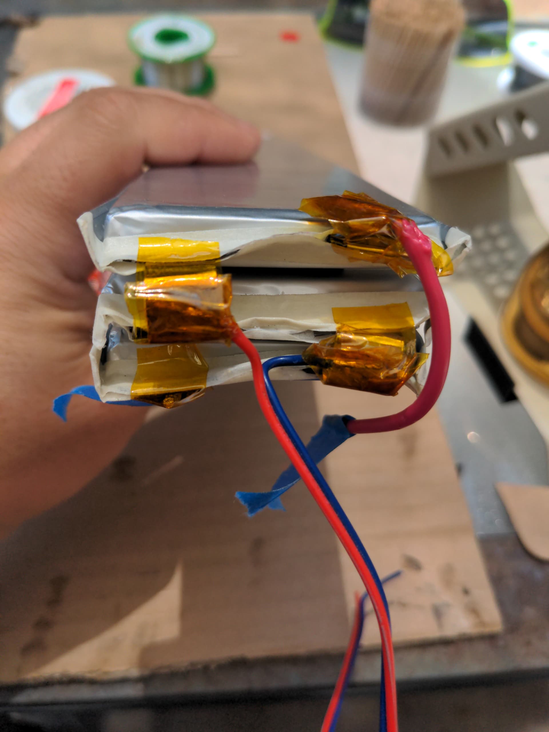
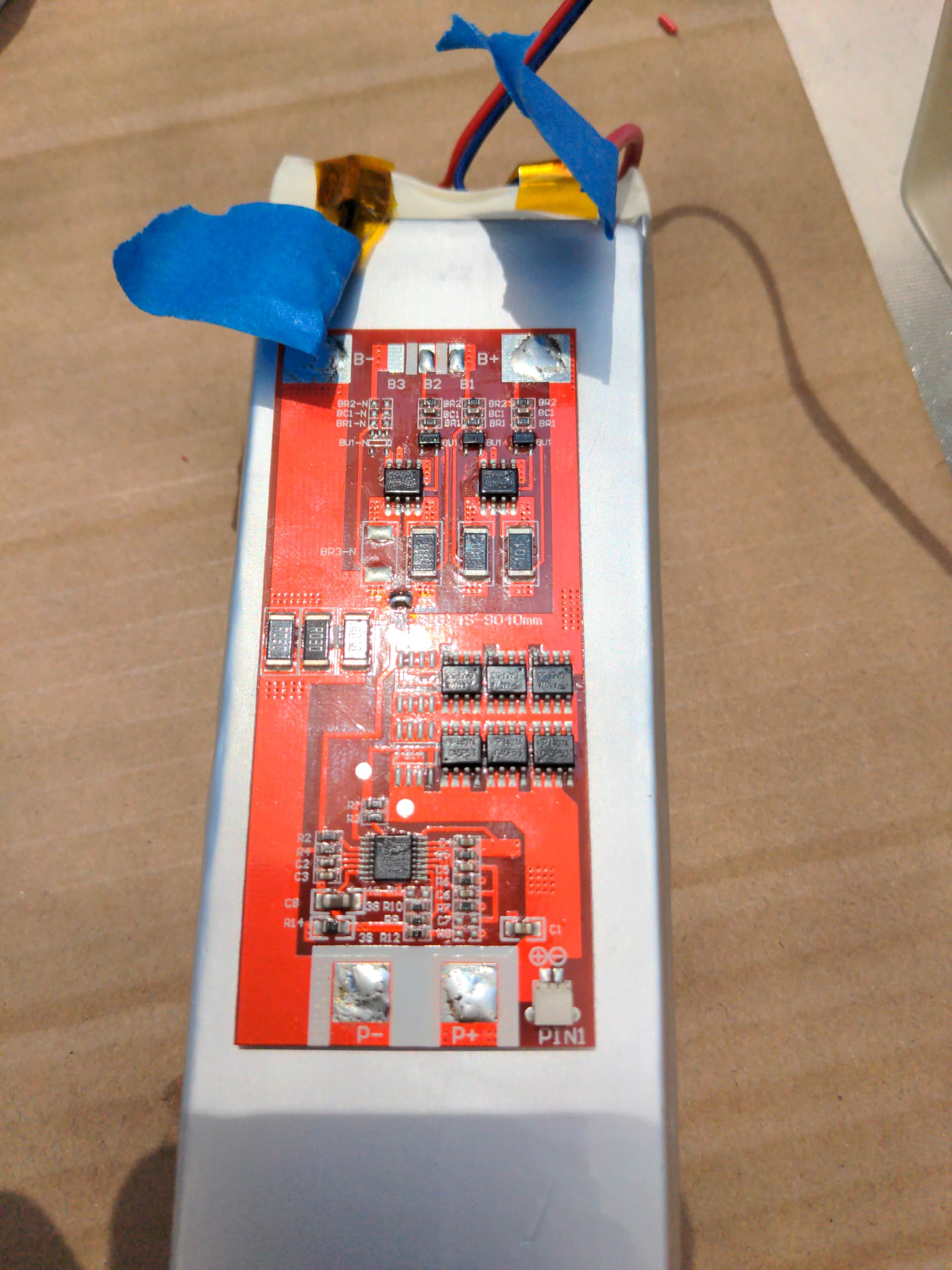
So, I’m going to build a battery pack for my LED enabled Playa Coat (fuzzy faux fur warm coat for night time in the desert at Burning Man), getting some 21Ah 2C pouch cells and 10A BMS from batteryspace.com. So going to spot weld (rather than solder) onto the pouch tabs, or even spot weld tabs together into 3s, however there’s a multitude of battery spot welders available.

There’s super cheap “12v powered” spot welder which is pretty bare and meant to be hooked up to ~12v power source. And it saying "there are 99 gears, but don’t go past 50) and only saying use 0.1-0.12mm strips, and I’m not getting the warm and fuzzies.

Some battery powered, well reviewed ones, which I’m wary of using battery powered ones like this, especially with the welding pens so completely bare of insulation. But it’s reasonably affordable for casual, occasional use.

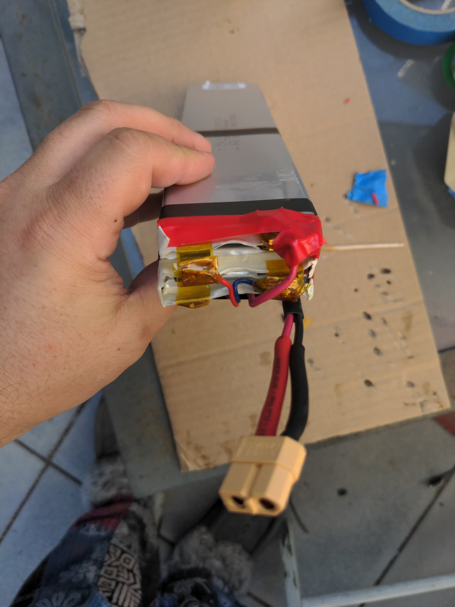
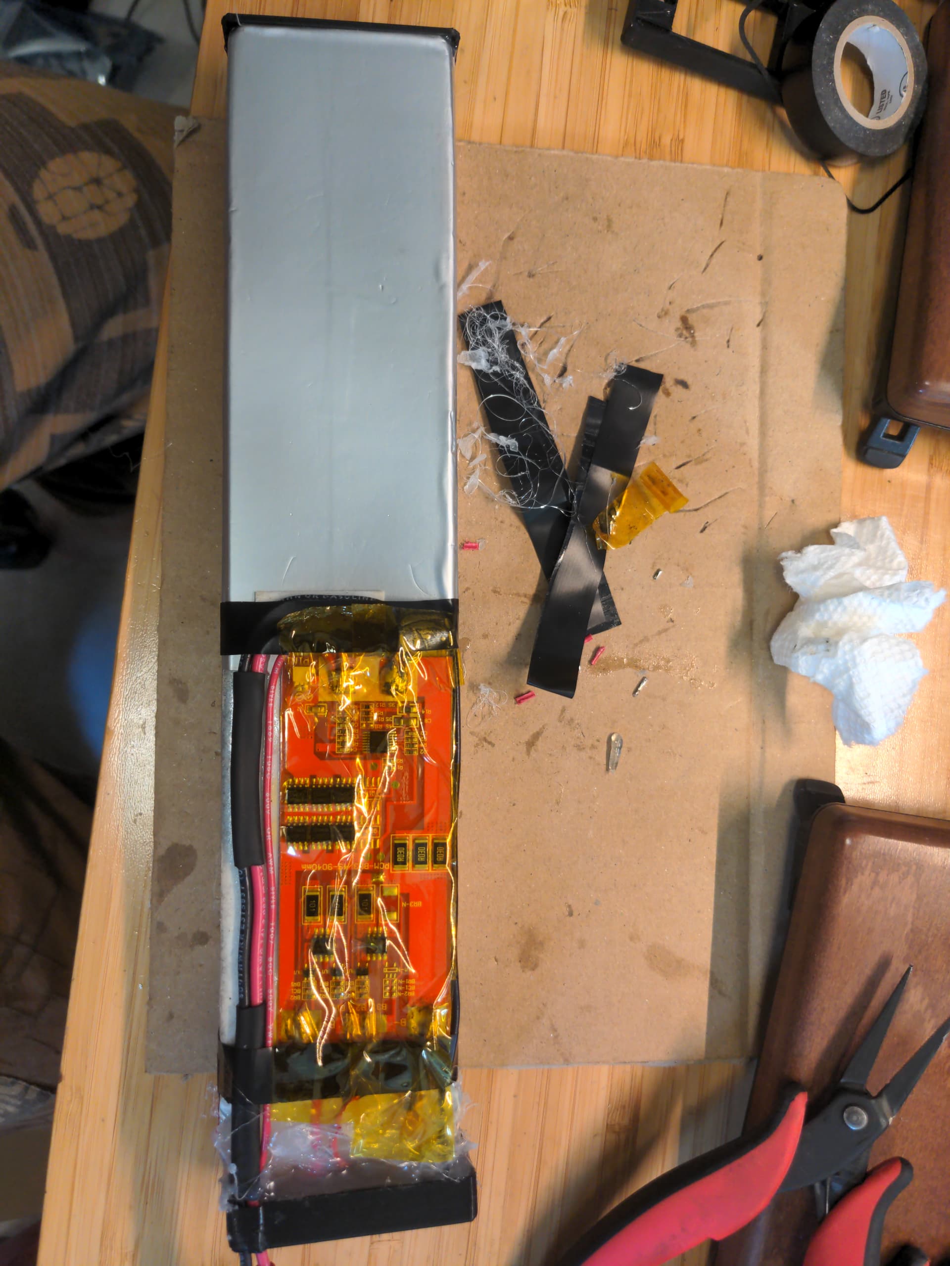
Then there’s a battery powered (2s) one with pedal that’s a bit more expensive, but still relatively affordable and makes me feel a lot safer with the pedal to only activate it when I have the tips where I want them. Seems safer, and this video shows it seems to handle up to 0.2mm strips pretty good. Although as we see from this teardown, the battery seems kinda crazily attached, directly to the MOSFET and 1 of the wires. At least they’re 30C cells, basically a short-circuit from the battery welder.

Then there’s a bench top style which is (relatively) a LOT more expensive, and physically bigger. Not too attractive to me due to size and cost, for casual use.

Interestingly enough there’s welding pen replacement which could be used with a lot of those generic smaller ones.

On the whole, I’m tempted towards the 5000W model. As long as I pay attention to the voltage, and don’t go below 6.8v or so, perhaps.

Those with more experience, what do ya’ll think? For small amounts of spot welding for batteries, what do you think?

I guess it depends on how much DIY you want. If you just want to eyeball the welds, you can use a car 12V battery, a motorcycle or car starter relay, and a push button. Add a pair of thick copper rods filed to points, and you have your contacts. Repeatability is the hard part here. I did see one person who made it slightly more predictable by adding a 555 timer (or arduino, whatever) so you can time how long the relay is powered for, though you still need to compensate for mechanical latency (i.e. you may depower the coil, but it takes time for the relay to actually release).

If you want diy but plan to do a lot of cells (read: dozens to hundreds) you can consider an upgrade to tungsten (welding) electrodes and some sort of clamping assembly to keep the contacts lined up straight.

Another option is to find a stash of old mainframe capacitors (i.e. 100k uF), and you can get repeatable welds by charging them up to a specific voltage, then discharging them through a high current relay (see above). This way no timing is required, just a power supply where you can set the voltage. Note that SuperCaps do not work for this purpose; they have high internal resistance limiting your current.

The cheap ones with FETs are prone to letting the magic smoke out; there’s a reason the production line models cost hundreds.

That “bench” unit; the “pull lever to apply contacts” is nifty, but it’s strictly a mechanical thing. I would not be surprised if there were 3d printable versions out there. indeed, that “pen” you link to seems to also be on thingiverse: Search Thingiverse - Thingiverse

A 300A thyristor “only” costs $30-50 but is far easier to trigger than a FET.

So I guess choose your poison? I happen to have a paper shopping bag full of 100k uF caps, so I eventually plan on going that route (note that in terms of bulky, 100k uF caps are NOT saving me any space)

Well, not interested in too much DIY on the spot welder itself, which is why I was asking some advice on which less expensive ones exist.

@Syonyk any opinions on any of the ones I have above?

I’m not really sure why you need one. If the cells have tabs already on them, it’s fine to solder to the tabs for assembly. That’s what they’re there for. I’m a stickler for spot welding, but only to the ends of 18650s. Comes with tabs? Do whatever.

Not having played in the lower end spot welder arena, I’ve got no particular advice on those. They’re all pretty sketchy looking, but I’m certain my unit would qualify as such to someone who’s used far higher end units.

The battery powered units are probably highly dependent on what the characteristics of the battery you attach are, and they do look mostly like “power electronics destroyers” to me, but for some limited use, they should be fine.

@Syonyk Oh, so pouch cells like this with the tabs, you think are perfectly fine to solder? Should be fine to solder tabs together, to produce the 3s pack?

Call battery space and double check, but I’d expect those to be fine to solder to, if you’re not taking forever about it. Those tabs don’t conduct heat terribly well.

Oh cool, I was thinking they’d conduct heat well enough to be a concern. But yeah, put some solder paste, tin the width of the with just a little bit, then paste the other side and flip over and hold together with some insulated needle pliers enough to keep them together/touching and apply heat to get them to solder together and I expect it’ll be fine then. My expectation will be probably 0.25C, hopefully less so I can get the run-time I’m wanting out of them. I’ve got a 5a CC/CV charger I’m going to use for charging it, so should be able to get it charged up during the day fine. I’ll just have a charging spot where I just plug it in in the morning after I wake up, and it’ll have plenty of time to charge up and balance.

Ok, so far so good, got the tabs soldered together, got balance wires solder on and then covered them all with Kaptan tape. Got the main +/- (14awg, rather overspecced) power leads soldered on securely and in place ready for the BMS connection.

@Syonyk, quick question, is there a particular order I should solder on the leads to the BMS on the battery side? I’ve got ~1/2" foam double sided tape holding the cells together, should I add some cardboard beneath the BMS to attach to the side of one of the cells? Or can I just use the foam tape to tape directly to the cell? I covered the few pads on the bottom with Kaptan tape already.

Once the BMS is on, I’ll add the power leads (going to use XT60, bit smaller than Anderson, tape those leads together/in place, then use hot glue on everything on the top to hold it all in place. I have some large shrink tubing on the way, I’ll use some cardboard & rubber to act as end caps on the bottom/top to help protect everything.

Am I missing anything?

Pics?

Unless the BMS comes with directions saying otherwise, I’d do negative, positive, then balance leads.

I wouldn’t add cardboard - if you’ve got a couple layers of insulation with the battery wrappers, double sticky tape, and Kaptan tape, just go straight to the BMS from there.

You shouldn’t need the cardboard for end caps. Either use some thin plywood, or just the rubber. IMO, cardboard has no business being around a battery.

Documentation for the BMS is pretty minimal. Good info on the specs and basic hookup diagram, but nothing on order of connection or what not.

Here’s the top of the pack, where I’ll eventually fill in with hot glue to keep everything in place.

Here’s more or less where I plan to put the BMS, sounds like just using the double-sided foam tape. I was going to just use 2 strips, but I can use more to help ensure that any kind of pressure won’t flex it to make contact, somehow. Shouldn’t regardless, but safety is better. I’m going to run the power output up along one side of the BMS (so slightly offset the BMS from center) and then cross over the B+ and out the center-ish of the top.

For the bottom/top caps, I do have a bit of 1/4" plywood laying about I could cut to size. Sadly I don’t think I have any thin plastic I could use. Hm, I could 3D print some 1-2mm caps, think that’d work better?

EDIT: @Syonyk Here’s after I’ve stuck the BMS on and soldered on the connectors. Strangely, I get no voltage reading across the P +/-, although I get proper 11.24v across the B +/-, and proper reading across each cell using the balancing leads.

I’d put the foam tape under the entire width of the BMS for protection. If it’s got a flat back, that should be fine.

As for no voltage… no idea! Not familiar with that BMS. Is that a switch connector in the lower right?

@Syonyk I’ve got 2 strips of foam on either side running the full length if the BMS.

As for a switch… Well, I have the product page and documentation link above, doesn’t mention anything about the PIN1 connector seems likely its a monitoring connector, but I can’t say for sure.

After I have the power soldered on. Next will be some hear shrink on the power, tape/stick down the main power, and then email them about the BMS and why there’s no P +/- voltage

EDIT: So emailed them, and then saw they have an actual phone number, so I tried that, and spoke with a nice guy who, after talking with, said I need to put it on the charger to “shock it”, e.g. kick start the PCM so it’ll start working. Make some sense as a safety measure, don’t have things turn on from the battery power when hooking it up, since theoretically the cells could be excessively low and just turning on the PCM stuff might be bad to do. So I’ll finish getting everything in order, and not jury rig anything just to put it on the charger.

Makes sense. Hopefully that solves it!

Yup, that did it. Soldered up a proper charge cable between the charger and the XT60 (battery), put it on the charger (12.6v CV/1a CC), got up to 1a CC on the screen steady. Turned it off, unplugged it, and measure the battery out voltage and it was at 11.24v. Perfect!

I decided I’m going to add a small momentary switch and battery meter, and just verified that that PIN1 connector is to battery voltage. Not sure I already have connector, so I’ll just solder the meter leads to the P +/-. I’ll 3D print up a ‘top’ to the battery pack which will hold the switch button and meter, and hot-glue the crap out of everything on top to hold it all in place. I think I’ll print up a mini bottom as well, make it look the same. Might as well.

It’s kinda liberating/nerve wracking to do up this all myself :slight_smile:

And because pics or it didn’t happen…


.

Excellent! Good work!

Have a healthy respect for lithium, and you’ll generally be fine. People who are “scared enough of it to be really careful” tend to not have problems. People who are super casual about it (often on a certain video site) scare me, because they encourage a type of casualness that lithium doesn’t often tolerate for long.

Lithium doesn’t really scare me. But I have a lot of respect for it, and I “verify twice, spot weld once” when building packs, because a dead short on lithium is something to avoid at all costs.

What’s this going for, again? Glowing pimp jacket? :stuck_out_tongue:

Ha! So to speak, yeah. Although I’m re-thinking this battery pack, was doing a fitting this evening, and brought the pack along. It’s looong. Having a place to fit it without it bumping up against my leg or arm or what not is a challenge it seems. Contemplating getting a pair (one for each side) of these or more likely, due to cost, these, even though it’s not quite as

Of course, maybe the usb packs, or this one or this, I guess I just hadn’t researched sufficiently large packs (with multiple outputs, assuming they can maintain full output on each port). I was also originally thinking 60led/m, and I’ve got 30led/m on the way, max 9W/m, assuming (probably extra) 10m and 1/2 brightness, and so perhaps 45W, more likely 20-35W in practice, since all of the colors won’t be on at the same time for each pixel. And probably a good bit less than 10m in total is my expectation.

Which for the same cost or less, I can actually get 2 pairs, keep the other 2 in my pack in case they run out. And don’t need external 5v conversion circuitry. Simpler and easier really, and simpler to charge up with a bunch of USB chargers in the trailer.

Anyways, good experience to build this pack, and I’ll still have a good use for it, can help power lights on my bike easily enough, or something like that.

Sooo…almost done! I mis-calculated the heatshrink tube size, rather drastically over, from what I need. So, time to buy some more. I suppose I might eventually have use for 90mm (before shrinking) tube…

So here’s the finished pack after adding the 3d printed top/bottom, and battery monitor with momentary button on top, and a buncha hot glue in the top to provide some support and hold everything evem more in place. Also being paranoid, added Kaptan tape over the entire BMS.

Slick! Nice build! No fancy voltmeter based state of charge gizmo?

Thought about doing that, but then decided I didn’t want to have to be bothered to manage math/thinking when I’ve had more than a few drinks. It’s specified for 3s, so I know when there’s no bars left that it’s real low, but does still have a bit. And with the BMS it’ll help protect from over discharge.

When battery voltage is over N3.3V,it will illuminate 1 block electricity quantity (note:N represents battery quantity)
When battery voltage is over N
3.5V,it will illuminate 2 blocks electricity quantity
When battery voltage is over N3.7V,it will illuminate 3 blocks electricity quantity
When battery voltage is over N
3.9V,it will illuminate 4 blocks electricity quantity
When battery voltage is less than N*3.3V,4 blocks display will be off;it represents battery is less than 3.3V,and you can charge the battery

EDIT: The momentary button is actually a fraction of a millimeter below the top, but close enough up that if I push hard with my finger/nail it’ll make contact. Glued in with E6000, and then the flange on the PCB of it overlaps it, with more E6000, and then a bunchaton of hot glue filling it all in. That switch isn’t going anywhere!

Now just waiting for that heatshrink, should be here Saturday :slight_smile: